3 - 49
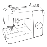
Upper shaft, Needle bar and Presser foot unit
Application of Assembly
Application
Application
1-15 Attachment of BH spring
1. Set the BH spring 1 to the base holder assy 2 with the screw 1.
*Key point
• Check that align the boss 3 of the base holder assy 2 with
the positioning hole of the BH spring 1.
1
3
1 2
1
Screw, Bind
M3X6
1-16
Attachment of Needle bar crank rod assy / Thread take-up lever
1. Set the thread take-up lever 1 to the needle bar crank rod assy 2 with the
screw 1.
*Key point
• The screw 1 is reverse threaded.
2. Set the needle bar crank rod assy 2 to the needle bar block 3.
Apply EPNOC AP (N) 0 to the shaft of the needle
bar crank.
Small amount
XC8387***
Apply EPNOC AP (N) 0 to the shaft of the thread
take-up lever.
Small amount
XC8387***
Apply EPNOC AP (N) 0 to the thread take-up
lever attachment face (left screw attachment face)
of the needle bar crank.
Small amount
XC8387***
1
1
1
2
2
3
Screw, Flat
SM3.57L
 Loading...