2 - 30
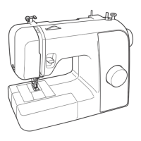
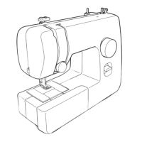
Upper shaft, Needle bar and Presser foot unit
Basic of Assembly
Basic
Basic
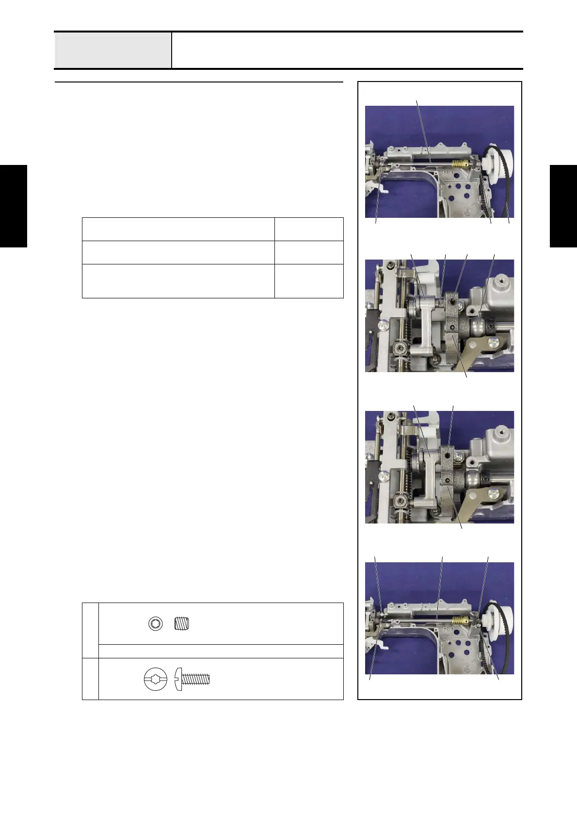
3 Attachment of Upper shaft assy
1. Pass the timing belt 1 to the upper shaft assy 2.
2. Set the thread take-up counter weight 3 to the needle bar crank rod assy
4.
3. Set the lower shaft bushing 5 and the lower shaft bushing 6 to the 2
positioning parts of the arm bed.
4. Align the D cut face 7 of the needle bar crank rod assy 4 with the screw
hole on the thread take-up counter weight 3, and then tighten the screw
1.
5. Set the 2 bushing pressers 8 to the arm bed, and then secure them with the
2 screws 2.
→Refer to 3 - 50 of the Assembly.
Apply FBK OIL RO 100 to the matching section of
the upper shaft and the lower shaft bushing 5.
2 drops
Apply FBK OIL RO 100 to the left and right end of
the lower shaft bushing 6.
2 drops
Apply FBK OIL RO 100 to the sliding surface of
the needle bar crank rod assy 4 and the thread
take-up counter weight 3.
2 drops
1
Hex wrench 2.5mm
2
3
14 7
3
4 1
5
2
6 1
2
2
8
82
6
Set Screw, Socket (FT)
M5X5
Taptite, Bind S
M4X10
 Loading...