2-138
COPYRIGHT
©
2001 CANON INC. 2000 2000 2000 2000 CANON CLC5000 REV.0 JAN. 2001
CHAPTER 2 NEW FUNCTIONS
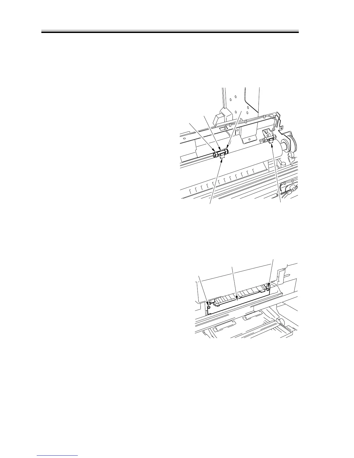
b.Removing the Fixing Main Thermistor (Upper) and Sub Thermistor (Upper)
1) Open the upper fixing roller unit. (See
the instructions on how to open the up-
per fixing roller unit on the CLC1000
service manual chapter 4.)
2) Remove the two fixing main thermistor
fixings [1].
3) Free the thermistor cord from the cord
retainer [2]; then, detach the fixing main
thermistor (upper) [3].
Note:
The sub thermistor (upper) [4] may be
removed in the same way.
F02-610-06
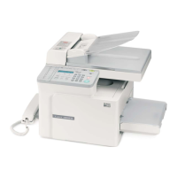
c.Removing the Fixing Main Thermistor (Lower) and Sub Thermistor (Lower)
1) Open the front left cover, and shift
down the fixing lever; then, slide out the
fixing unit.
2) Remove the two screws [1], and detach
the fixing inlet guide mounting base [2].
F02-610-07
[1]
[1]
[2]
[3]
[4]
[1]
[1]
[2]



 To Next Page