2-179
CHAPTER 2 NEW FUNCTIONS
COPYRIGHT
©
2001 CANON INC. 2000 2000 2000 2000 CANON CLC5000 REV.0 JAN. 2001
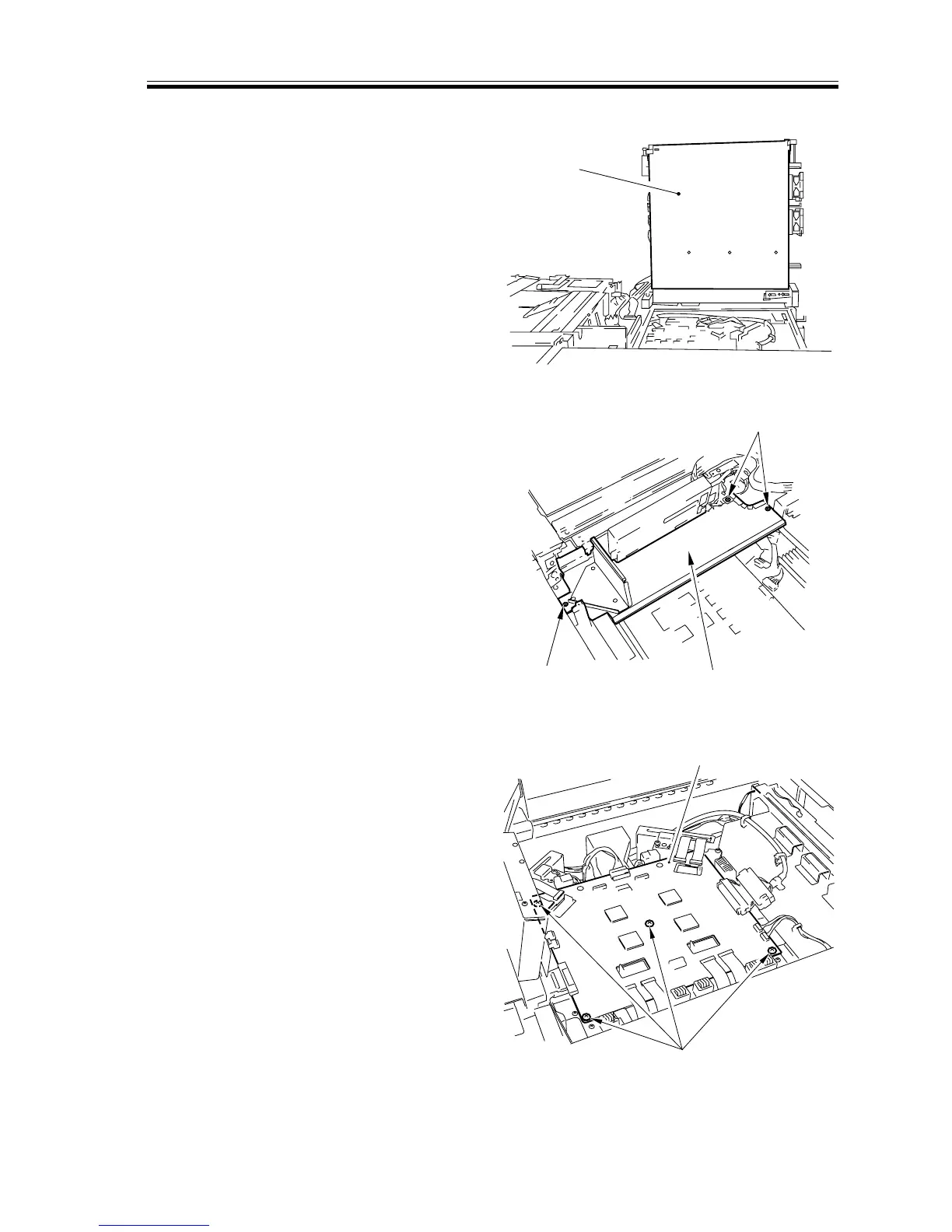
j. Removing the Video Controller PCB
1) Secure the digital unit [1] as indicated
in the figure. (See the instructions on
the preparatory work for the laser unit.)
[1]
[2]
[2]
[3]
[4]
[5]
F02-706-42
2) Remove the three screws [2], and detach
the air duct plate [3].
F02-706-43
3) Disconnect all connectors and remove
the four mounting screws [4] from the
video controller PCB; then, detach the
video controller PCB [5].
F02-706-44