2-181
CHAPTER 2 NEW FUNCTIONS
COPYRIGHT
©
2001 CANON INC. 2000 2000 2000 2000 CANON CLC5000 REV.0 JAN. 2001
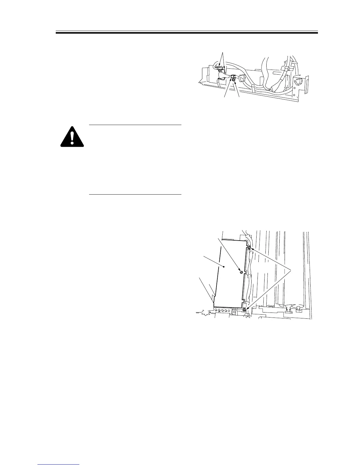
9) Remove the screw [8], and detach the
cable fixing plate [9] at the rear.
10) Disconnect the two connectors [10] on
the rear side.
[10]
[9]
[8]
F02-706-47
After mounting the image cor-
rection CCD unit, execute the
following in service mode:
FUCN>INSTALL (2nd
sheet)>REG-PAPER (pattern
read position auto adjustment);
then, turn off and on the power
to correct the image position.
l. Removing the Transfer High-Voltage Transformer (HVT1)
1) Open the transfer unit. (See the instruc-
tions on how to open the transfer unit.)
2) Remove the screw [1], and detach the
insulating cover [2] for the transfer
high-voltage transformer; then, removed
the two screws [3].
[1]
[2]
[3]
F02-706-48