COPYRIGHT
©
2001 CANON INC. 2000 2000 2000 2000 CANON CLC5000 REV.0 JAN. 2001
CHAPTER 5 TROUBLESHOOTING IMAGE FAULTS/MALFUNCTIONS
5-47
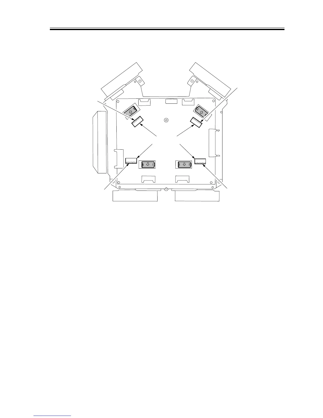
4) Set the laser power checker switch to ‘2’.
5) Insert the laser power checker with its light-receiving face oriented as indicated in F05-
208-03.
F05-208-03
6) Insert the lead wire of the laser power checker into the Digital Multimeter, and set it to
the 200 mV range.
7) Start service mode, and execute ‘POWER’ and ‘1/2 POWER’ of ‘6 LASER’ under
‘FUNC’.
8) Check to make sure that the reading of the Digital Multimeter is ‘POWER: 44.8 ±0.4
mV, 1/2 POWER: 20.0 ±0.2 mV’. If the readings are not as specified, make the follow-
ing adjustments:
Bk laser unit
C laser unit
M laser unit
Y laser unit
Laser power checker
Light-
receiving
face
Light-
receiving
face
Light-
receiving
face
Light-
receiving
face