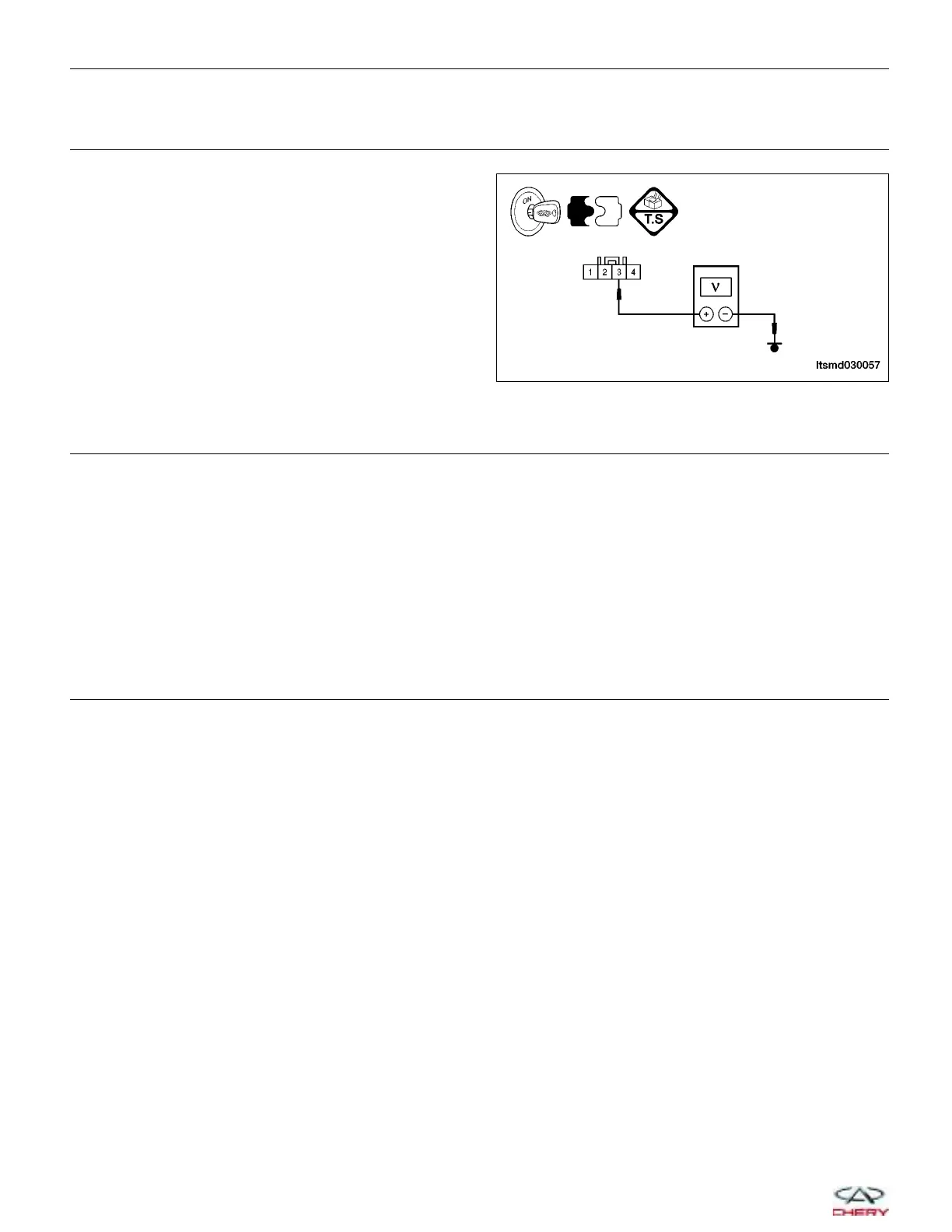
4.
CHECK THE MAP SENSOR POWER SUPPLY CIRCUIT FOR AN OPEN OR SHORT
• Check the voltage between terminal 3 and ground
in the MAP sensor connector E-033 terminal side.
• Approximately 5 V should exist.
Is the check result normal?
Yes
>> Go to the next step.
No
>>
Repair or replace the circuit for an open,
short to ground or short to power in har-
ness or connectors.
If circuit is normal, go to the next step.
5.
CHECK THE MAP SENSOR GROUND CIRCUIT FOR AN OPEN
• Turn ignition switch off.
• Disconnect the MAP sensor electrical connector E-001.
• Check the continuity between terminal 1 in MAP sensor connector E-033 and terminal 17 in ECM connector
E-601.
• Continuity should exist.
Is the check result normal?
Yes
>> Go to the next step.
No
>> Repair or replace the circuit for an open in harness or connectors.
6.
CHECK THE MAP SENSOR OUTPUT SIGNAL CIRCUIT FOR AN OPEN OR HIGH RESISTANCE
• Check the continuity between MAP sensor terminal 4 and ECM terminal 37.
• Continuity should exist.
Is the check result normal?
Yes
>> Go to the next step.
No
>> Repair or replace the circuit for an open or high resistance in harness or connectors.
DIAGNOSIS & TESTING
LTSMD030057
03–50
Chery Automobile Co., Ltd.
 Loading...


