7.
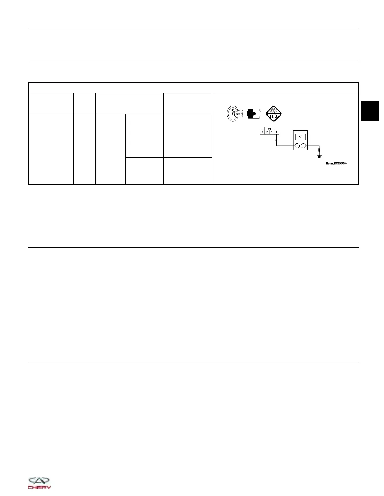
CHECK THE MAP SENSOR SIGNAL
• Check MAP sensor signal between terminal 4 and ground harness side, under the following test conditions:
MAP SENSOR OUTPUT SIGNAL
MAP SENSOR
TERMINAL
NO.
ITEM CONDITION
DATA
(DC VOLTAGE)
4
MAP
sensor
Engine:
Running
Engine
running:
Idle
Press
accelerator
pedal
slowly
Approximately
1.3 V
Press
accelerator
pedal
quickly
Up to
approximately 4
V
(instantaneous)
Is the check result normal?
Yes
>> Go to step 9.
No
>> Go to the next step.
8.
CHECK OR REPLACE THE MAP SENSOR
• Check the sensor as follows:
− Remove the sensor mounting bolt.
− Remove the sensor.
− Visually check the sensor for blockage or damage, and clean the pressure port of the sensor.
Is the check result normal?
Yes
>>
Replace the MAP sensor with a known good MAP sensor.
Select view DTC on the X-431 screen.
− If DTC P0105 or P0106 is not present, the system is OK.
− If DTC P0105 or P0106 is present, go to step 9.
No
>> Clean or replace the MAP sensor.
9.
CHECK DTC
• With the X-431 scan tool, read ECM DTCs.
• Refer to 9DTC Confirmation Procedure9.
Is DTC P0105 or P0106 still present?
Yes
>> Replace the ECM.
NOTE : The Immobilizer control module must be matched to the new ECM (See ECM Removal & Instal-
lation in Section 03 Electronic Engine Controls).
No
>>
The system is now operating properly.
Reassemble the vehicle and road test to verify the customers complaint is repaired.
DIAGNOSIS & TESTING
03
03–51
Chery Automobile Co., Ltd.
 Loading...


