6.
CHECK INJECTOR POWER SUPPLY CIRCUIT FOR OPEN OR SHORT
• Turn ignition switch on.
• Check injector supply voltage between terminal 1 and ground, terminal side.
• Battery voltage should exist.
Is the check result normal?
Yes
>> Go to step 8.
No
>> Go to the next step.
7.
DETECT MALFUNCTIONING PART
• Check the following for a possible malfunction:
− Fuse EF5
− Main relay
− Front fuse and relay box A-040
− Harness for an open or short to ground between injector and fuse
Is the check result normal?
Yes
>> With X-431, check the system, If OK, go to the next step.
No
>> Repair or replace malfunctioning part(s).
8.
CHECK INJECTOR CONTROL CIRCUITS FOR OPEN
• Check injector control circuit voltage.
• 3.6 V should exist.
Is the check result normal?
Yes
>> Go to step 10.
No
>> Go to the next step.
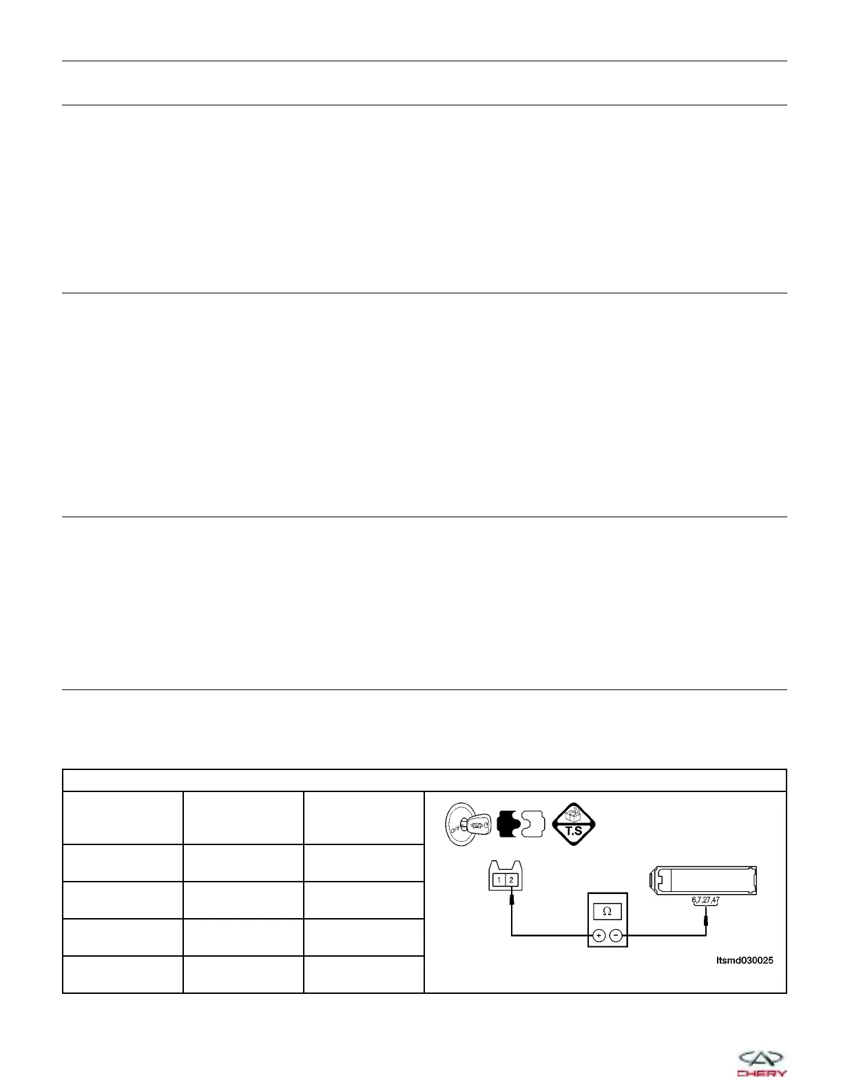
9.
DETECT MALFUNCTIONING PART
• Turn ignition switch off.
• Disconnect the ECM electrical connector.
• Check the continuity between the following terminals:
CHECK INJECTOR CIRCUIT
INJECTOR NO
ECM
TERMINAL
INJECTOR
TERMINAL
1 27 2
2 6 2
3 7 2
4 47 2
DIAGNOSIS & TESTING
03–108
Chery Automobile Co., Ltd.
 Loading...


