• Continuity should exist.
Is the check result normal?
Yes
>> Go to the next step.
No
>> Repair circuit for an open in harness or connectors.
10.
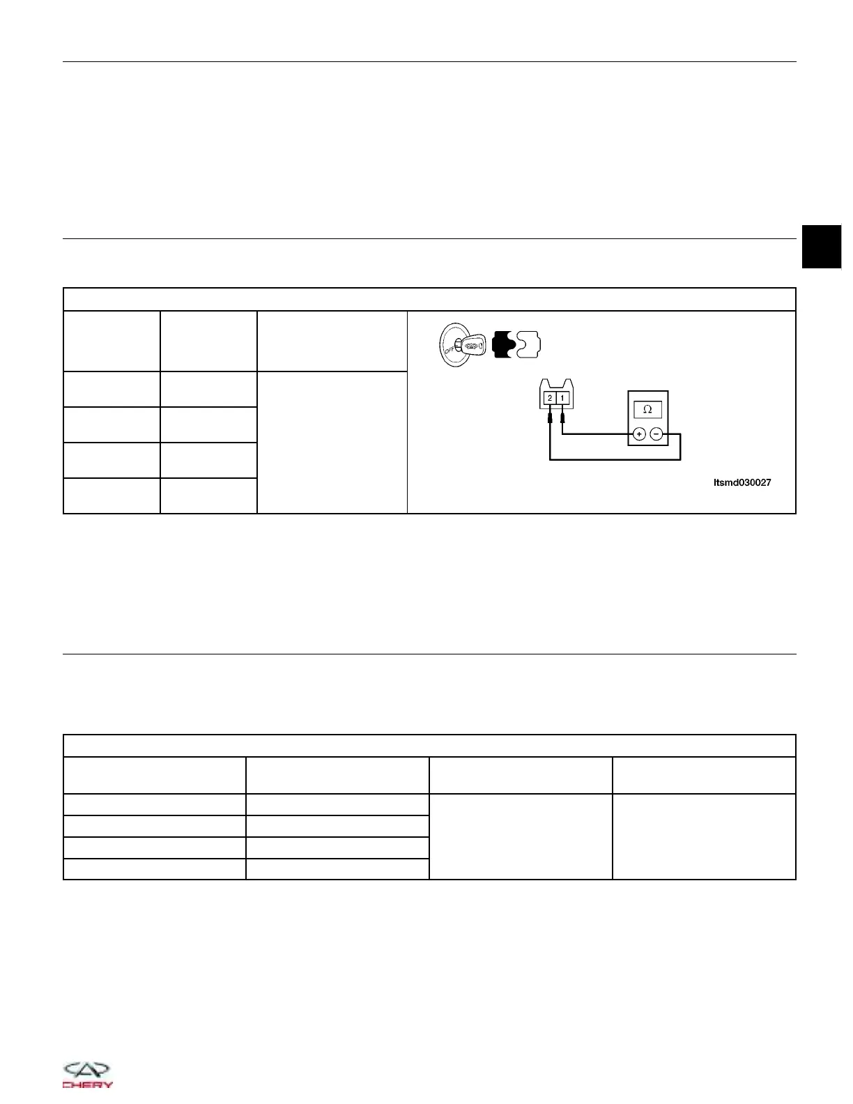
CHECK INJECTOR
• Check resistance between the following injector terminals, component side:
FUEL INJECTOR RESISTANCE
INJECTOR
NO.
INJECTOR
TERMINAL
RESISTANCE
(APPROXIMATELY) V
(20°C)
1 1 & 2
11 - 16
2 1 & 2
3 1 & 2
4
1 & 2
Is the check result normal?
Yes
>> Go to the next step.
No
>> Replace injector.
11.
CHECK INJECTOR OPERATION
• Connect the ECM electrical connector.
• Connect injector connector.
• Check injector voltage under the following conditions:
INJECTOR REFERENCE DATA
TERMINAL NO. INJECTOR NO CONDITION
DATA (AVERAGE DC
VOLTAGE)
6 2
• Engine is running
• Warm-up condition
• Idle
• Accelerate suddenly
Voltage: 11 - 14 V
7 3
27 1
47 4
Is the check result normal?
Yes
>> Go to the next step.
No
>> Replace injector.
DIAGNOSIS & TESTING
03
03–109
Chery Automobile Co., Ltd.
 Loading...


