4.
CHECK TPS POWER SUPPLY CIRCUIT - (2)
• Turn ignition switch off.
• Disconnect the ECM electrical connector.
• Check continuity between TPS terminal 3 and ECM terminal 32.
• Check continuity between TPS terminal 3 and ECM terminal 73.
• Continuity should exist.
Is the check result normal?
Yes
>> Go to the next step.
No
>> Repair or replace the open circuit.
5.
CHECK TPS POWER SUPPLY CIRCUIT - (3)
• Check harness for a short to power and short to ground, between the following terminals:
TPS POWER SUPPLY CIRCUIT
ECM TERMINAL TPS/APPS TERMINAL
32 or 73 TPS terminal 3
32 or 73 APP sensor terminal 3
33 APP sensor terminal 6
Is the check result normal?
Yes
>> Go to the next step.
No
>> Repair or replace short to ground or short to power in harness or connectors.
6.
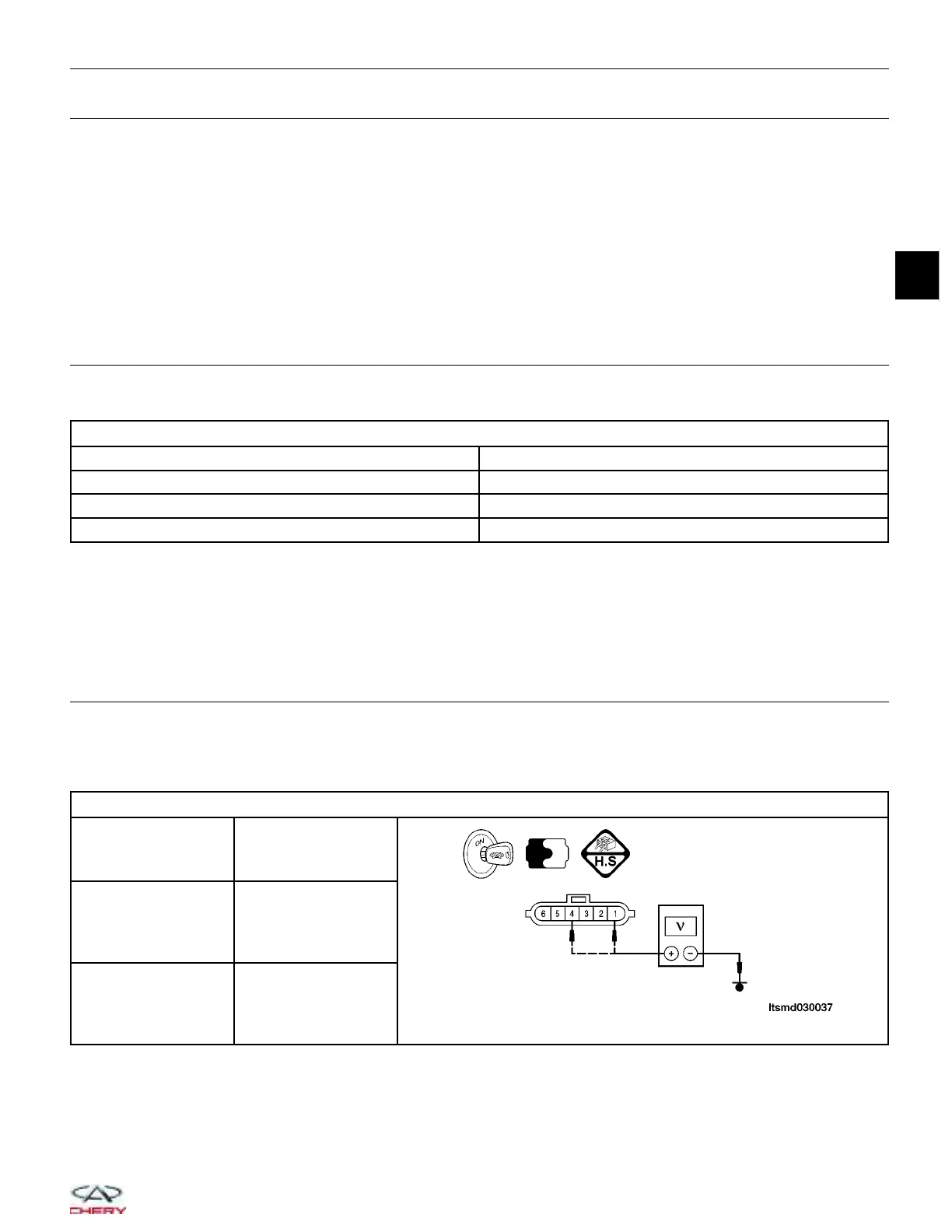
CHECK THE APP SENSOR
• Connect all harness connectors that have been disconnected.
• Turn ignition switch on.
• Install a digital multimeter to the APP sensor as shown in the following:
APP SENSOR CIRCUIT
ECM TERMINAL APPS TERMINAL
16
APP sensor terminal
4
40
APP sensor terminal
1
DIAGNOSIS & TESTING
03
03–159
Chery Automobile Co., Ltd.