9.
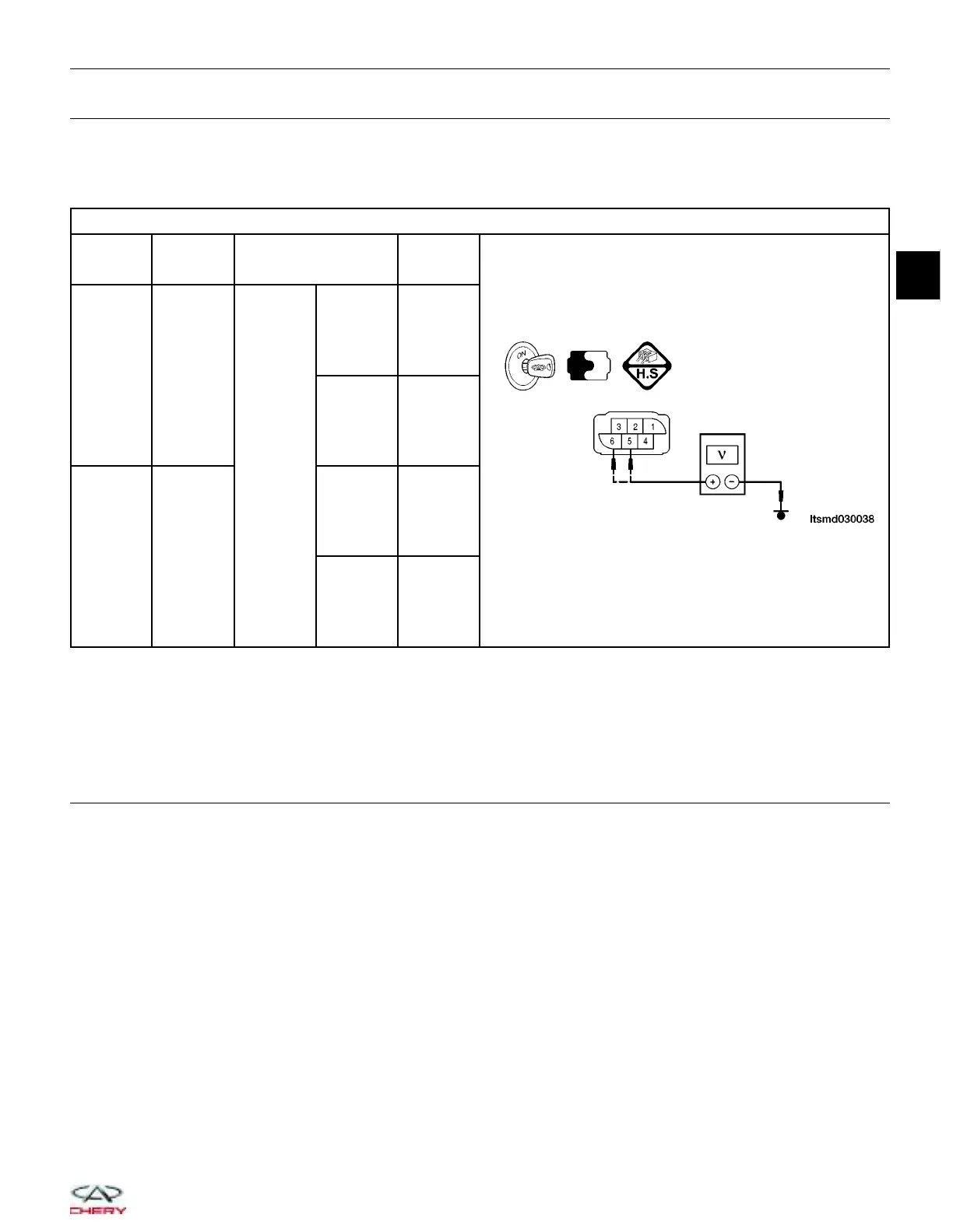
CHECK TPS
• Connect all harness connectors that have been disconnected.
• Turn ignition switch on.
• Check voltage between ECM terminals 54 (TPS 1), 38 (TPS 2) and ground under the following conditions:
TPS REFERENCE DATA
TPS
TERMINAL
NO.
ITEM CONDITION
VOLT (DC
VOLTAGE)
5
Electronic
throttle
control
actuator
(TPS2)
Ignition
switch:
ON
Engine:
Stopped
Accelerator
pedal:
Fully
released
4.24 V
Engine:
Stopped
Accelerator
pedal:
Fully
depressed
0.72 V
6
Electronic
throttle
control
actuator
(TPS1)
Engine:
Stopped
Accelerator
pedal:
Fully
released
0.74 V
Engine:
Stopped
Accelerator
pedal:
Fully
depressed
4.62 V
Is the check result normal?
Yes
>> Go to the next step.
No
>> Replace the electronic throttle control actuator, and perform throttle valve position learning.
10.
CHECK DTC
• With the X-431 scan tool, read ECM DTCs.
• See DTC Confirmation Procedure.
Is DTC P1545 still present?
Yes
>> Replace the ECM.
NOTE : The Immobilizer control module must be matched to the new ECM (See ECM Removal & Instal-
lation in Section 03 Electronic Engine Controls).
No
>>
The system is now operating properly.
Reassemble the vehicle and road test to verify the customers complaint is repaired.
DIAGNOSIS & TESTING
03
03–161
Chery Automobile Co., Ltd.