3.
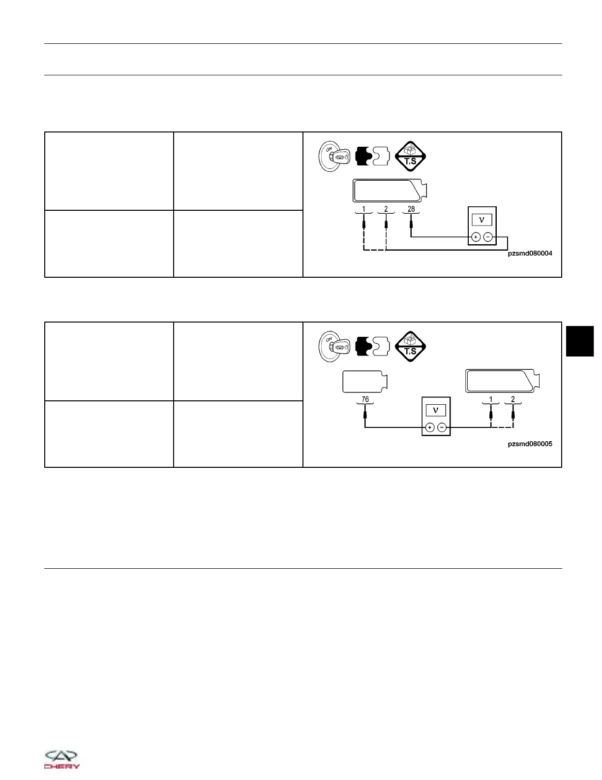
CHECK AMT CONTROL MODULE POWER SUPPLY
• Turn ignition switch on.
• Check the voltage between terminal 28 of the AMT control module connector E-602, and terminal 1 & 2 of the
AMT control module, terminal side.
AMT CONTROL MODULE
CONNECTOR TERMINAL
VOLTAGE
28 and 1 & 2 Less than 9 V
• Check the voltage between terminal 76 of the AMT control module connector E-603, and terminal 1 & 2 in the
AMT control module electrical connector E-602, terminal side.
AMT CONTROL MODULE
CONNECTOR TERMINAL
VOLTAGE
76 and 1 & 2 Less than 9 V
Is the voltage less than 9 V?
Yes
>> Go to step 4.
No
>> Replace the AMT control module.
4.
CHECK SYSTEM VOLTAGE
• Start the engine, raise the engine speed to above 1000 RPM.
• Measure the charging system voltage at the battery positive and negative terminals.
Is the voltage less than 9 V?
Yes
>> Check the charging system.
No
>> Go to the next step.
DIAGNOSIS & TESTING
08
08–69
Chery Automobile Co., Ltd.
 Loading...


