3.
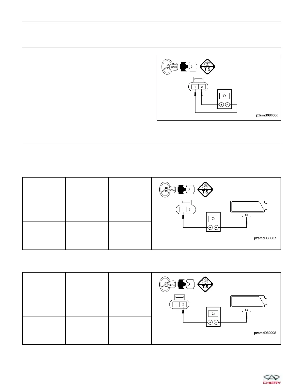
CHECK CLUTCH SPEED SENSOR RESISTANCE
• Check the resistance between clutch speed sensor
terminal 1 and 2 in the sensor electrical connector.
• 450 ± 50 V (20 °C) should exist.
Is the check result normal?
Yes
>> Go to the next step.
No
>> Replace the sensor.
4.
CHECK CLUTCH SPEED SENSOR SIGNAL CIRCUIT
• Turn ignition switch off.
• Disconnect the AMT control module electrical connector.
• Check the continuity between the clutch speed sensor terminal 1 and the AMT control module electrical connec-
tor terminal 38.
CLUTCH
SPEED
SENSOR
TERMINAL
AMT CONTROL
MODULE
CONTINUITY
1 38 Yes
• Check the continuity between the clutch speed sensor terminal 2 and the AMT control module electrical connec-
tor terminal 50.
CLUTCH
SPEED
SENSOR
TERMINAL
AMT CONTROL
MODULE
CONTINUITY
2 50 Yes
DIAGNOSIS & TESTING
PZSMD080006
08–76
Chery Automobile Co., Ltd.



 To Next Page