• Check the harness for a short to power and short to ground.
Is the check result normal?
Yes
>> Go to the next step.
No
>> Repair or replace the circuit for an open, short to power or short to ground.
5.
CHECK CLUTCH SPEED SENSOR SIGNAL
• Connect the AMT control module and clutch speed sensor electrical connectors.
• Start the vehicle and perform the following:
− Engine: 2000 RPM
− Vehicle: 50 km/h
− Gear: 3
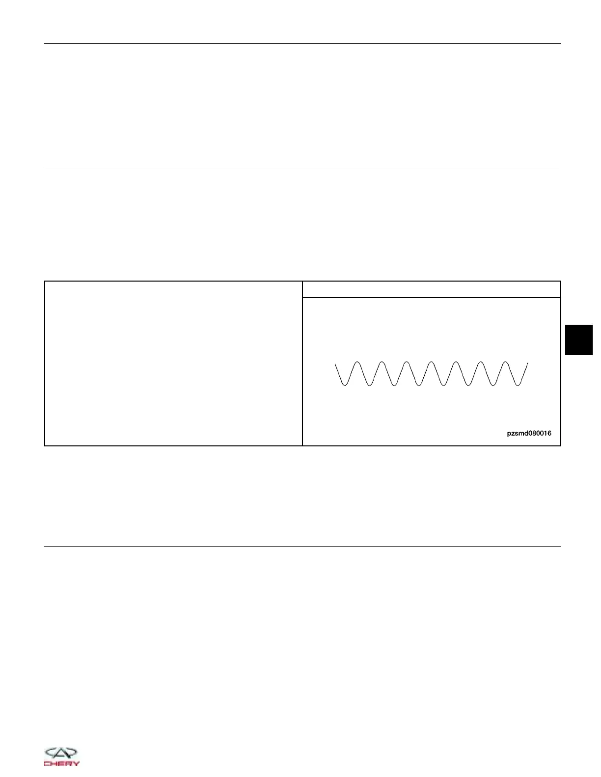
• Check the clutch speed sensor signal between sensor terminal 1 or 2 and ground in the sensor electrical con-
nector with an oscilloscope.
• Make sure the wave shape and signal voltage is normal.
ENGINE ANALYZER (KES-200)
CLUTCH SPEED SENSOR SIGNAL
Is the check result normal?
Yes
>> Go to step 9.
No
>> Go to the next step.
6.
CHECK CLUTCH SPEED SENSOR
• Loosen the sensor mounting bolt.
• Remove the sensor.
• Visually inspect the sensor for any missing, chipped or damaged components.
• Visually inspect for interference between the AMT clutch signal ring and clutch speed sensor.
Is the check result normal?
Yes
>>
Replace the clutch speed sensor.
Monitor the clutch speed sensor signal on the oscilloscope.
− If the clutch speed sensor signals were normal, the system is OK.
− If the clutch speed sensor signals were still irregular or missing, go to step 7.
No
>> Replace the clutch speed sensor and repair the AMT signal ring if needed (excessive run-out of the
signal ring in the AMT could result in interference between the signal ring and the sensor causing damage to the
sensor).
DIAGNOSIS & TESTING
08
08–77
Chery Automobile Co., Ltd.



 To Next Page