2.
CHECK GEAR POSITION SENSOR ELECTRICAL CONNECTOR
• Stop the vehicle and turn ignition switch off.
• Disconnect the gear position sensor electrical connector P-008 (1).
• Inspect the electrical connector for damage.
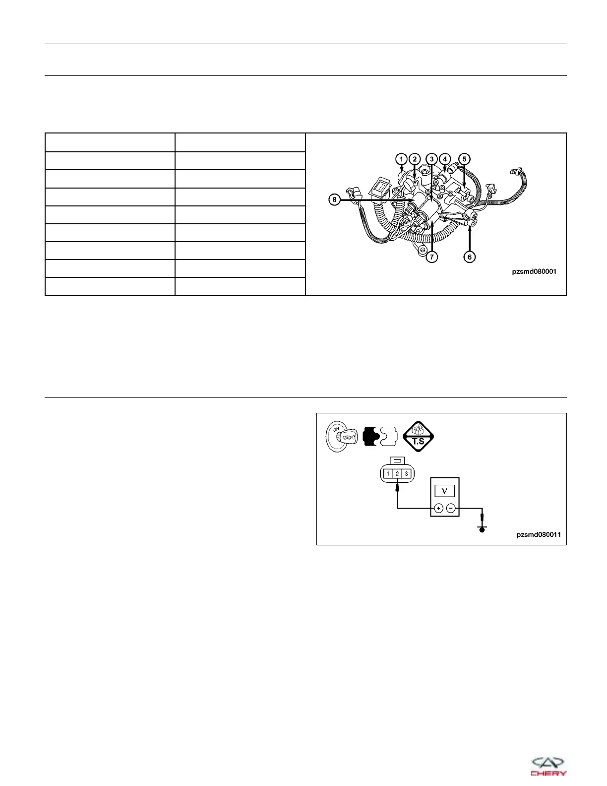
NUMBER SOLENOID/SENSOR
1 Gear position sensor
2 Shift position sensor
3 Clutch solenoid valve
4 Hydraulic pressure sensor
5 Gear solenoid valve
6 Clutch position sensor
7 Gear solenoid valve
8 Shift solenoid valve
Is the electrical connector OK?
Yes
>> Go to the next step.
No
>> Repair or replace the electrical connector as necessary.
3.
CHECK GEAR POSITION SENSOR POWER SUPPLY
• Turn ignition switch on.
• Check power supply between terminal 2 of the gear
position sensor connector P-008, terminal side and
ground.
• 5 V should exist.
Is the check result normal?
Yes
>> Go to the next step.
No
>> Repair or replace the circuit for an open,
short to power or short to ground.
DIAGNOSIS & TESTING
PZSMD080011
08–82
Chery Automobile Co., Ltd.