4.
CHECK SENSOR GROUND CIRCUIT
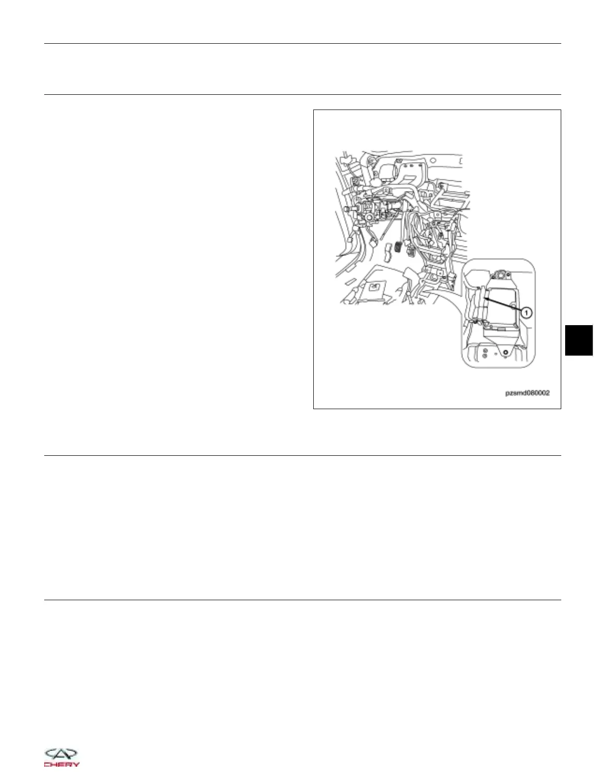
• Disconnect the AMT control module (1) electrical
connector E-602 and E-603.
• Check the continuity between terminal 1 of the gear
position sensor connector P-008, and terminal 66 of
the AMT control module connector E-603, terminal
side.
• Check the sensor ground circuit for a short to
power.
Is the check result normal?
Yes
>> Go to the next step.
No
>> Repair the circuit for an open or short to
power in the harness or connectors.
5.
CHECK GEAR POSITION SENSOR SIGNAL CIRCUIT
• Check the continuity between terminal 3 of the gear position sensor connector P-008, and terminal 39 of the
AMT control module connector E-602, terminal side.
• Continuity should exist.
• Check the signal circuit for a short to ground and short to power supply.
Is the check result normal?
Yes
>> Go to step 6.
No
>> Check the harness for an open or short to ground or short to power supply in harness or connectors.
6.
CHECK THE GEAR POSITION SENSOR
• Replace the gear position sensor with a known good sensor.
• Start the vehicle and monitor the value of 9GEAR POSITION9 with the X-431 scan tool.
Is the check result normal?
Yes
>> Go to the next step.
No
>> Check the AMT gear condition, the gap between the sensor and the signal component, the gear
selection lever.
DIAGNOSIS & TESTING
PZSMD080002
08
08–83
Chery Automobile Co., Ltd.