5.
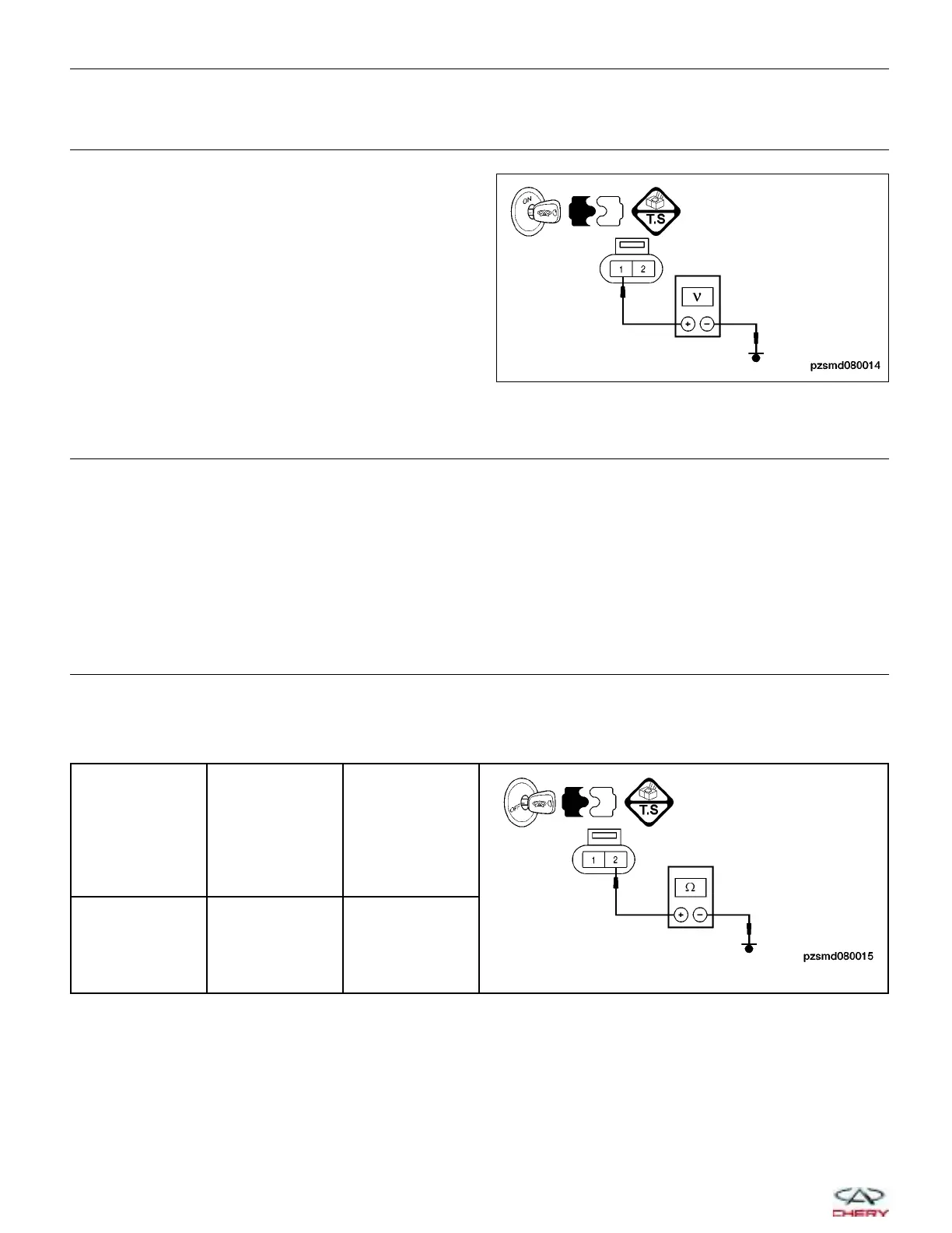
CHECK CLUTCH SOLENOID VALVE POWER SUPPLY
• Turn ignition switch on.
• Operate the scan tool X-431 to actuate the clutch
solenoid valve.
• Check for voltage between terminal 1 of the clutch
solenoid valve connector P-006 and ground, termi-
nal side.
• Voltage should be more than 12 V.
Is the check result normal?
Yes
>> Go to step 7.
No
>> Go to the next step.
6.
DETECT MALFUNCTIONING PART
• Check the following:
− Harness connectors E-705 and P-100, terminal 8
− Harness open or short between AMT connector and clutch solenoid valve connector
Is the check result normal?
Yes
>> Go to the next step.
No
>> Repair or replace the circuit for an open, short to power or short to ground.
7.
CHECK CLUTCH SOLENOID VALVE GROUND CIRCUIT
• Turn ignition switch off.
• Disconnect the AMT control module electrical connector.
• Check for harness continuity between the following terminals:
AMT CONTROL
MODULE
TERMINAL
TERMINAL CONTINUITY
2 Ground Yes
• Check the harness for a short to power.
Is the check result normal?
Yes
>> Go to the next step.
No
>> Repair or replace the circuit for an open, short to power or short to ground.
DIAGNOSIS & TESTING
PZSMD080014
08–100
Chery Automobile Co., Ltd.
 Loading...


