3.
CHECK CLUTCH SOLENOID VALVE ELECTRICAL CONNECTOR
• Stop the vehicle and turn ignition switch off.
• Disconnect the clutch solenoid valve electrical connector P-006 (3).
• Inspect the electrical connector for damage.
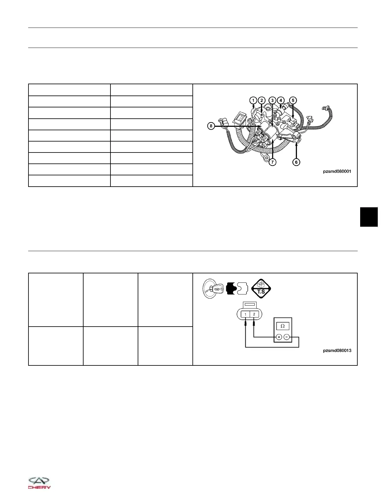
NUMBER SOLENOID/SENSOR
1 Gear position sensor
2 Shift position sensor
3 Clutch solenoid valve
4 Hydraulic pressure sensor
5 Gear solenoid valve
6 Clutch position sensor
7 Gear solenoid valve
8 Shift solenoid valve
Is the electrical connector OK?
Yes
>> Go to the next step.
No
>> Repair or replace the electrical connector as necessary.
4.
CHECK CLUTCH SOLENOID VALVE RESISTANCE
• Check the clutch solenoid resistance as shown in the following table:
AMT CLUTCH
SOLENOID
TERMINAL
CLUTCH
SOLENOID
VALVE
TERMINAL
VALUE
Resistance
( 23°C )
1 & 2
Standard value
(V)
Is the check result normal?
Yes
>>
Replace the clutch solenoid valve with a known good solenoid.
With the X-431, perform the solenoid actuate test.
− If the solenoid can be heard, the system is normal.
− If the solenoid can’t be heard, go to the next step.
No
>> Replace the clutch solenoid valve.
DIAGNOSIS & TESTING
08
08–99
Chery Automobile Co., Ltd.
 Loading...


