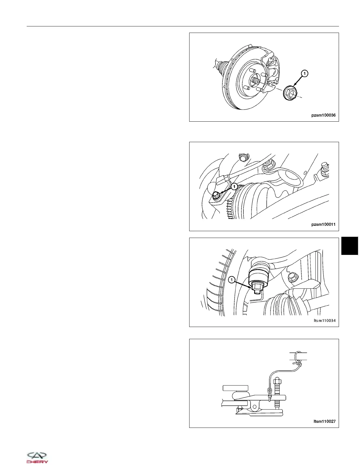
4. While a helper applies the brakes to keep the hub
from rotating, remove the front axle shaft hub nut
(1).
(Tighten: Axle shaft hub nut to 270 ± 20 N·m)
5. Access and remove the Front Brake Rotor (See Front Brake Rotor Remove & Installation in Section 12 Brakes).
6. Remove the wheel speed sensor retaining bolt (1)
and set the wheel speed sensor aside.
(Tighten: Wheel speed sensor bolt to 15 ± 2 N·m)
7. Remove the nut (1) attaching the outer tie rod end
to the steering knuckle.
(Tighten: Outer tie rod end to the steering knuckle
nut to 40 ± 5 N·m)
8. Using special tool CH-10002, separate the outer tie
rod end from the steering knuckle.
ON-VEHICLE SERVICE
PZSM100036
PZSM100011
LTSM110034
LTSM110027
10
10–7
Chery Automobile Co., Ltd.