12. Assembly is in the reverse order of disassembly.
Sub-Frame Assembly
Removal & Installation
NOTE :
The following special tools are required to perform the repair procedure:
• CH-10002 - Ball Joint Separator
WARNING!
Before removing the sub-frame assembly, properly support the engine and transaxle assembly.
1. Raise and support the vehicle.
2. Remove the wheel mounting nuts and the wheel assembly.
(Tighten: Wheel mounting nuts to 110 N·m)
3. Support the engine using an engine support fixture or suitable jack.
4. Remove the engine undercover and splash shields.
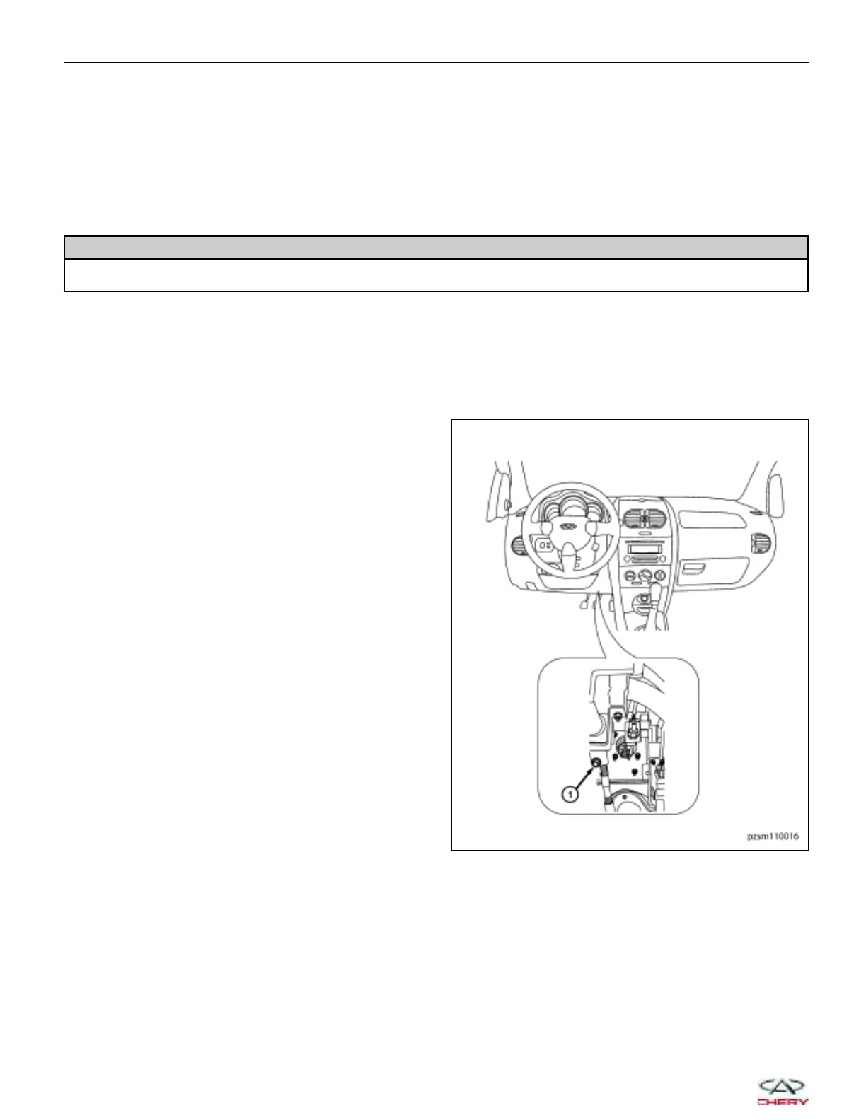
5. Remove the intermediate shaft coupling bolt (1) at
the steering gear.
(Tighten: Intermediate shaft coupling bolt to 25 ± 5
N·m)
ON-VEHICLE SERVICE
PZSM110016
10–18
Chery Automobile Co., Ltd.
 Loading...