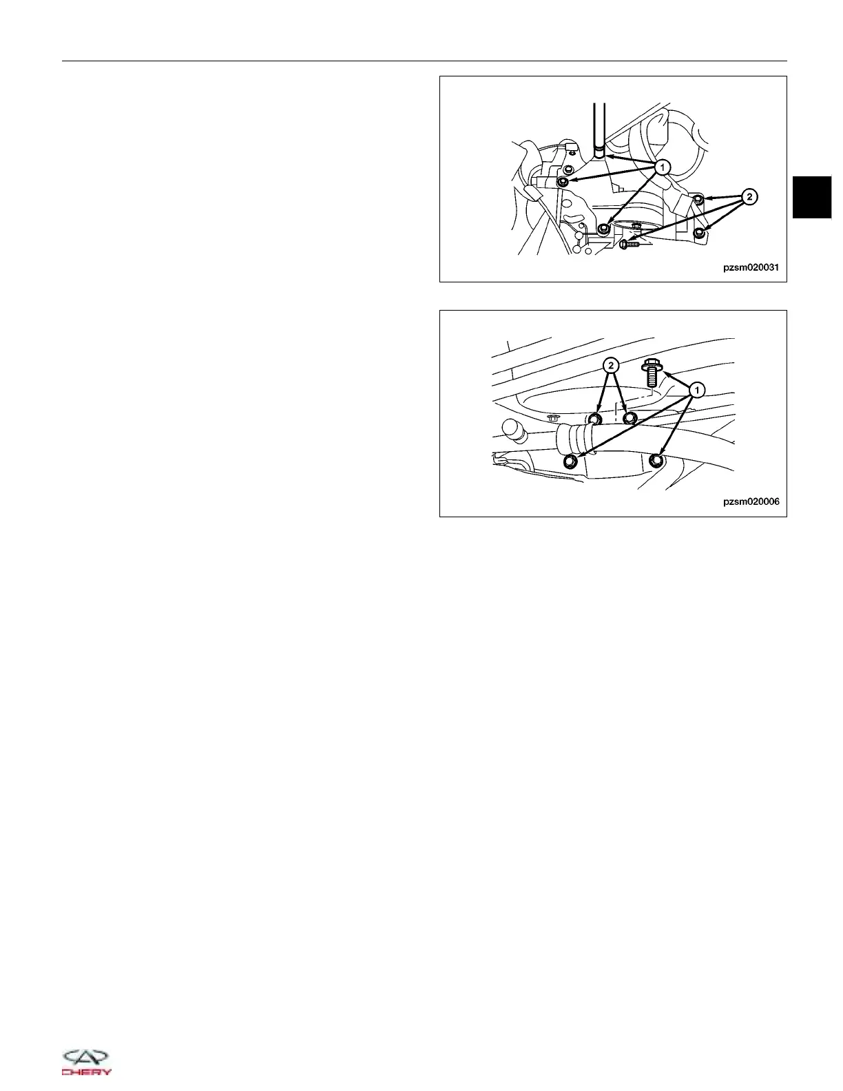
36. Remove the three left transaxle mount bolts (1)
and the three left transaxle mount bracket bolts (2).
(Tighten: Left transaxle mount bolt to 65 ± 5 N·m)
37. Using special tool CH-20001, remove the two right
engine mount bolts (1) and three right engine
mount bracket bolts (2).
(Tighten: Engine right mount bolt to 65 ± 5 N·m)
38. Verify all components between the engine and
vehicle are disconnected.
39. Remove the front sub-frame (See Front Sub-Frame
Removal & Installation in Section 10 Suspension).
40. Hoist the engine from the vehicle.
CAUTION:
Verify all electrical connectors are discon-
nected prior to engine/transaxle removal.
41. Separate the engine and transaxle.
42. Installation is in the reverse order of removal.
ON-VEHICLE SERVICE
PZSM020031
PZSM020006
02
02–39
Chery Automobile Co., Ltd.
 Loading...


