3.
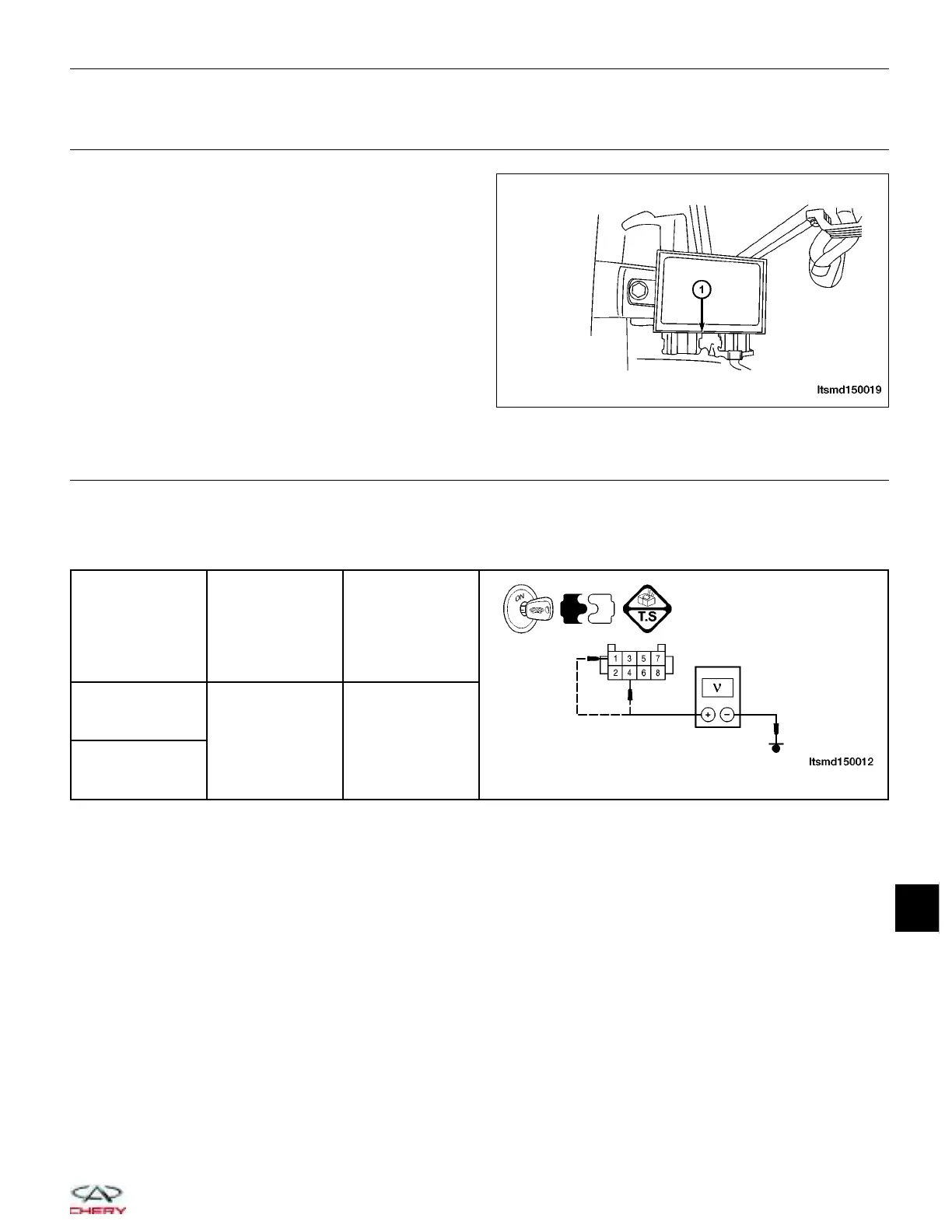
CHECK IMMOBILIZER CONTROL MODULE ELECTRICAL CONNECTOR
• Turn ignition switch off.
• Disconnect the Immobilizer control module electrical
connector C-025 (1).
• Inspect the electrical connector for damage.
Is the electrical connector OK?
Yes
>> Go to the next step.
No
>> Repair or replace the electrical connector
as necessary.
4.
CHECK IMMOBILIZER CONTROL MODULE POWER SUPPLY
• Connect the negative battery cable.
• Turn ignition switch on.
• Check voltage between the Immobilizer control module connector C-025, terminal 4, 1 and ground.
IMMOBILIZER
CONTROL
MODULE
TERMINAL
GROUND VOLTAGE
1
Ground
12 V should
exist
4
Is the check result normal?
Yes
>> Go to step 7.
No
>> Go to the next step.
DIAGNOSIS & TESTING
LTSMD150019
15
15–125
Chery Automobile Co., Ltd.