5.
CHECK IMMOBILIZER CONTROL MODULE POWER SUPPLY CIRCUIT
• Turn ignition switch off.
• Disconnect the negative battery cable.
• Check the continuity between the front fuse and relay box A-040, fuse SF1 (30A) and Immobilizer control mod-
ule connector C-025, terminal 1.
− Inspect front fuse and relay box A-040, fuse SF1 (30A) position (See Vehicle Wiring Harness Layout -
Engine Room Harness in Section 16 Wiring).
• Check harness continuity between body fuse box C-020, fuse F2 (10A) and Immobilizer control module connec-
tor C-025, terminal 4.
− Inspect body fuse box C-020, fuse F2 (10A) position (See Vehicle Wiring Harness Layout - Main Harness in
Section 16 Wiring).
• Continuity should exist.
• Check harness for short to ground.
• Continuity between Immobilizer control module power supply and ground should not exist.
Is the check result normal?
Yes
>> Go to the step 7.
No
>>
Check fuse F2 (10A), fuse 13 (10A) and fuse SF1 (30A). Verify the fuse is OK, If not OK, refer to the
wiring diagram to identify the possible causes of the shorted circuit.
Repair or replace the open or high resistance circuit or short to ground in harness or connectors.
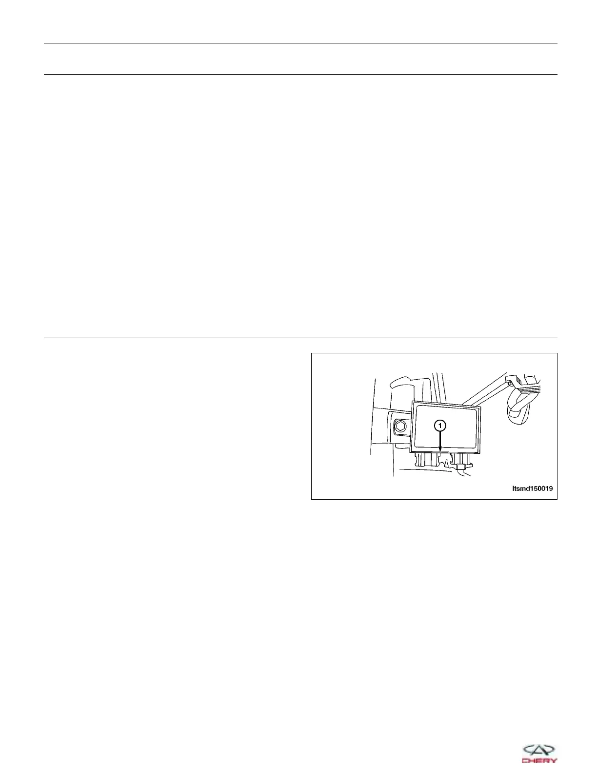
6.
CHECK IMMOBILIZER CONTROL MODULE ELECTRICAL CONNECTOR
• Turn ignition switch off.
• Disconnect the Immobilizer control module electrical
connector C-026 (1).
• Inspect the electrical connector for damage.
Is the electrical connector OK?
Yes
>> Go to the next step.
No
>> Repair or replace the electrical connector
as necessary.
DIAGNOSIS & TESTING
LTSMD150019
15–126
Chery Automobile Co., Ltd.