2.
CHECK IMMOBILIZER CONTROL MODULE DTC
• With the scan tool, view DTCs in the Immobilizer control module.
• Refer to DTC confirmation procedure.
Is DTC B3050 or B3053 present?
Yes
>> Go to the next step.
No
>> The conditions that caused this code to set are not present at this time (See Diagnostic Help in Sec-
tion 15 Body & Accessories).
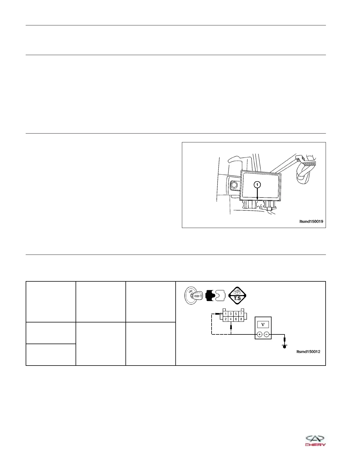
3.
CHECK IMMOBILIZER CONTROL MODULE ELECTRICAL CONNECTOR
• Turn ignition switch off.
• Disconnect the Immobilizer control module electrical
connector C-025 (1).
• Inspect the electrical connector for damage.
Is the electrical connector OK?
Yes
>> Go to the next step.
No
>> Repair or replace the electrical connector
as necessary.
4.
CHECK IMMOBILIZER CONTROL MODULE POWER SUPPLY
• Turn ignition switch on.
• Check voltage between the Immobilizer control module connector C-025, terminal 4, 1 and ground.
IMMOBILIZER
CONTROL
MODULE
TERMINAL
GROUND VOLTAGE
1
Ground
12 V should
exist
4
Is the check result normal?
Yes
>> Replace the Immobilizer control module and match the ECM to the Immobilizer control module (See
Immobilizer Control Module Removal & Installation in Section 15 Body & Accessories).
No
>>
For DTC B3050, go to the next step.
For DTC B3053, go to the step 6.
DIAGNOSIS & TESTING
LTSMD150019
15–134
Chery Automobile Co., Ltd.
 Loading...


