13-3
Catalyst 6500 Series Switch Software Configuration Guide—Release 8.7
OL-8978-04
Chapter 13 Configuring CEF for PFC2 and PFC3A
Understanding How Layer 3 Switching Works
The packet rewrite alters these five fields:
• Layer 2 (MAC) destination address
• Layer 2 (MAC) source address
• Layer 3 IP Time to Live (TTL) or IPX Transport Control
• Layer 3 checksum
• Layer 2 (MAC) checksum (also called the frame checksum or FCS)
Note Packets are rewritten with the encapsulation that is appropriate for the next-hop subnet.
If Source A and Destination B are on different VLANs and Source A sends a packet to MSFC2/MSFC3
to be routed to Destination B, the switch recognizes that the packet was sent to the Layer 2 (MAC)
address of MSFC2/MSFC3.
To perform Layer 3 switching, the switch rewrites the Layer 2 frame header, changing the Layer 2
destination address to the Layer 2 address of Destination B and the Layer 2 source address to the Layer 2
address of MSFC2/MSFC3. The Layer 3 addresses remain the same.
In IP unicast and IP multicast traffic, the switch decrements the Layer 3 TTL value by 1 and recomputes
the Layer 3 packet checksum. In IPX traffic, the switch increments the Layer 3 Transport Control value
by 1 and recomputes the Layer 3 packet checksum. The switch recomputes the Layer 2 frame checksum
and forwards (or for multicast packets, replicates as necessary) the rewritten packet to Destination B’s
VLAN.
These sections describe how the packets are rewritten:
• Understanding IP Unicast Rewrite, page 13-3
• Understanding IPX Unicast Rewrite, page 13-4
• Understanding IP Multicast Rewrite, page 13-4
Understanding IP Unicast Rewrite
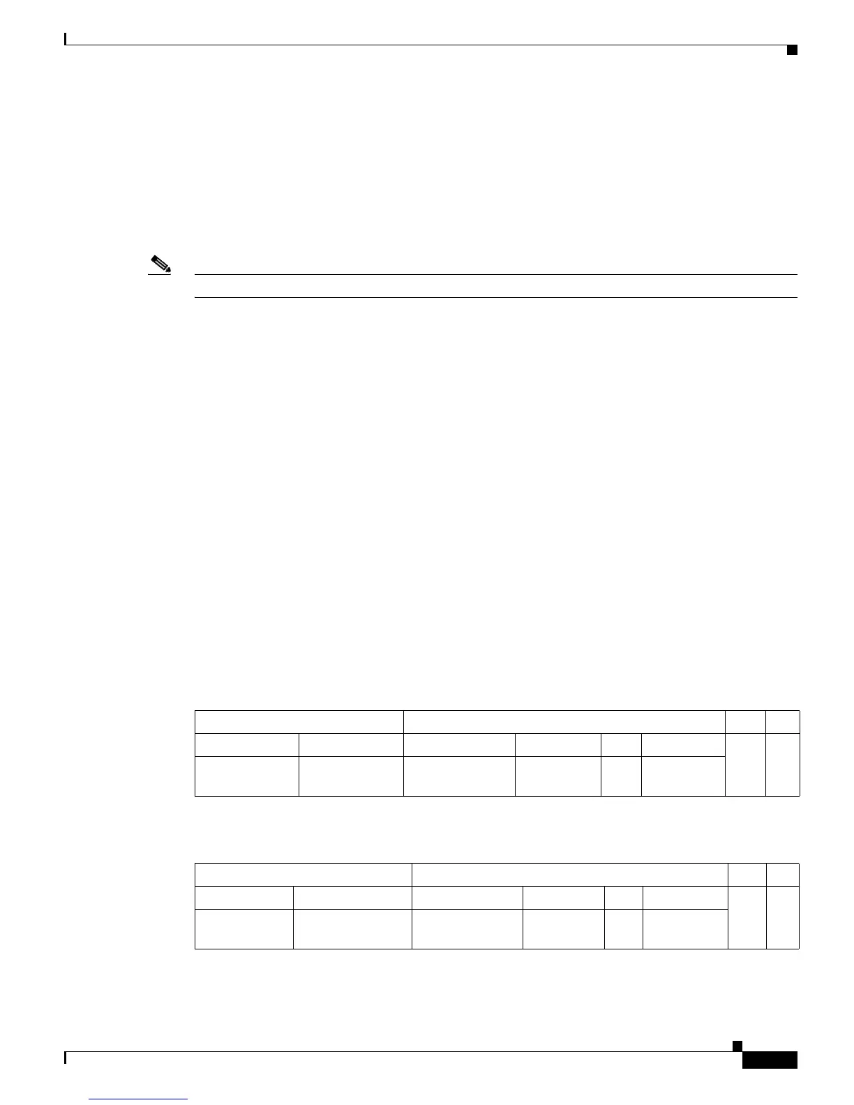
Received IP unicast packets are (conceptually) formatted as follows:
After the switch rewrites an IP unicast packet, it is (conceptually) formatted as follows:
Layer 2 Frame Header Layer 3 IP Header Data FCS
Destination Source Destination Source TTL Checksum
MSFC2/MSFC3
MAC
Source A MAC Destination B IP Source A IP n calculation1
Layer 2 Frame Header Layer 3 IP Header Data FCS
Destination Source Destination Source TTL Checksum
Destination B
MAC
MSFC2/MSFC3
MAC
Destination B IP Source A IP n-1 calculation2