11-2
Catalyst 6500 Series Switch Software Configuration Guide—Release 8.7
OL-8978-04
Chapter 11 Configuring VLANs
Understanding How VLANs Work
These sections describe VLANs:
• VLAN Ranges, page 11-2
• Configurable VLAN Parameters, page 11-3
• Default VLAN Configuration, page 11-3
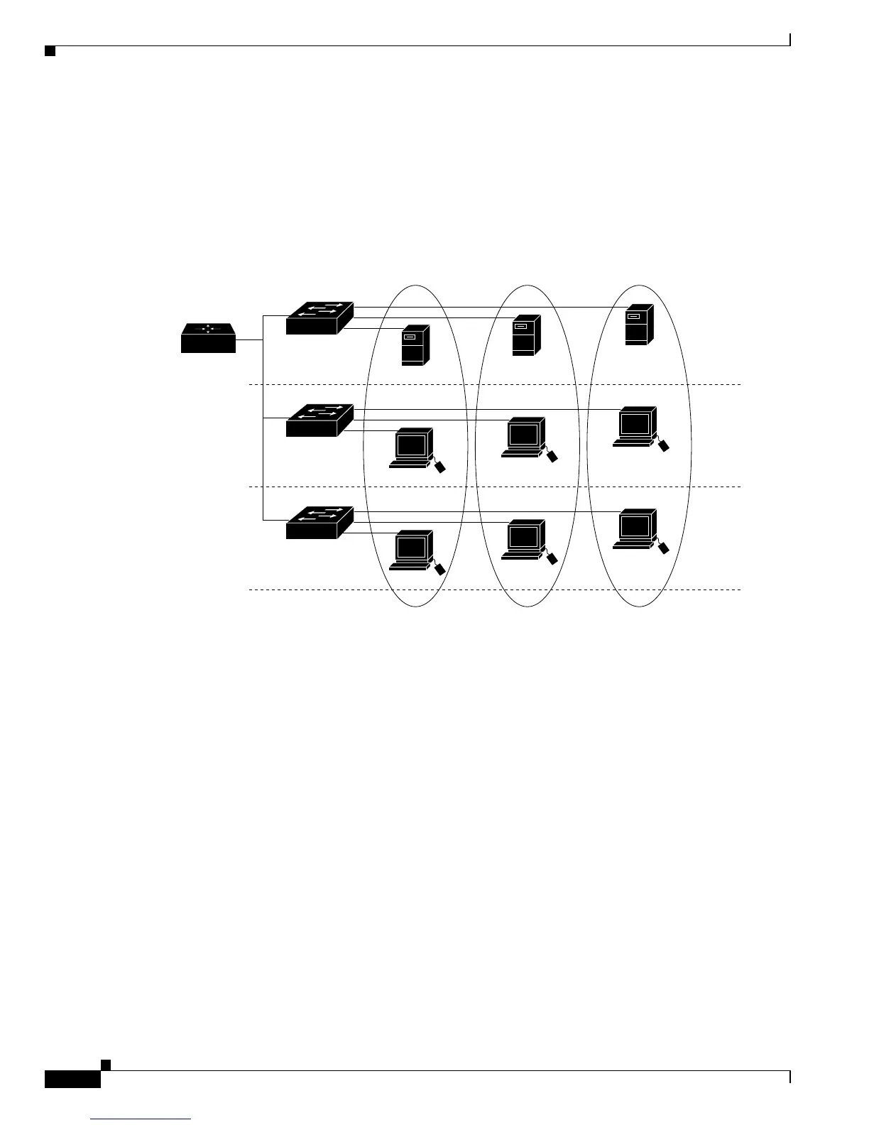
Figure 11-1 VLANs as Logically Defined Networks
VLANs are often associated with the IP subnetworks. For example, all the end stations in a particular IP
subnet belong to the same VLAN. The traffic between the VLANs must be routed. Port VLAN
membership on the switch is assigned manually on a port-by-port basis. When you assign the switch
ports to the VLANs using this method, it is known as port-based, or static, VLAN membership.
The in-band (sc0) interface of a switch can be assigned to any VLAN, so that you can access another
switch on the same VLAN directly without a router. Only one IP address at a time can be assigned to the
in-band interface. If you change the IP address and assign the interface to a different VLAN, the previous
IP address and VLAN assignment are overwritten.
VLAN Ranges
Catalyst 6500 series switches support 4096 VLANs in accordance with the IEEE 802.1Q standard. These
VLANs are organized into two ranges; you use each range slightly differently. Some of these VLANs
are propagated to other switches in the network when you use a management protocol, such as the VLAN
Trunking Protocol (VTP). Other VLANs are not propagated and you must configure them on each
applicable switch.
VLANs are divided into the following two ranges:
• Normal-range VLANs: 1–1023