14-11
Catalyst 6500 Series Switch Software Configuration Guide—Release 8.7
OL-8978-04
Chapter 14 Configuring MLS
Understanding How Layer 3 Switching Works
The PFC prevents multicast traffic in flows that are completely Layer 3 switched from reaching the
MSFC, reducing the load on the MSFC. The show ip mroute and show mls ip multicast commands
identify completely Layer 3-switched flows with the text string “RPF-MFD.” Multicast Fast Drop
(MFD) indicates that from the perspective of the MSFC, the multicast packet is dropped because it is
switched by the PFC.
For all completely Layer 3-switched flows, the PFC periodically sends the multicast packet and byte
count statistics to the MSFC, because the MSFC cannot record the multicast statistics for completely
switched flows, which it never sees. The MSFC uses the statistics to update the corresponding multicast
routing table entries and to reset the appropriate expiration timers.
MLS Examples
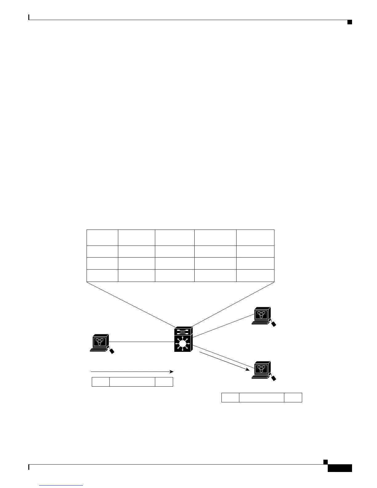
Figure 14-1 shows a simple IP MLS network topology. In this example, Host A is on the Sales VLAN
(IP subnet 171.59.1.0), Host B is on the Marketing VLAN (IP subnet 171.59.3.0), and Host C is on the
Engineering VLAN (IP subnet 171.59.2.0).
When Host A initiates an HTTP file transfer to Host C, an MLS entry for this flow is created (this entry
is the second item in the MLS cache shown in Figure 14-1). The PFC stores the MAC addresses of the
MSFC and Host C in the MLS entry when the MSFC forwards the first packet from Host A through the
switch to Host C. The PFC uses this information to rewrite the subsequent packets from Host A to
Host C.
Figure 14-1 IP MLS Example Topology
Figure 14-2 shows a simple IPX MLS network topology. In this example, Host A is on the Sales VLAN
(IPX address 01.Aa), Host B is on the Marketing VLAN (IPX address 03.Bb), and Host C is on the
Engineering VLAN (IPX address 02.Cc).