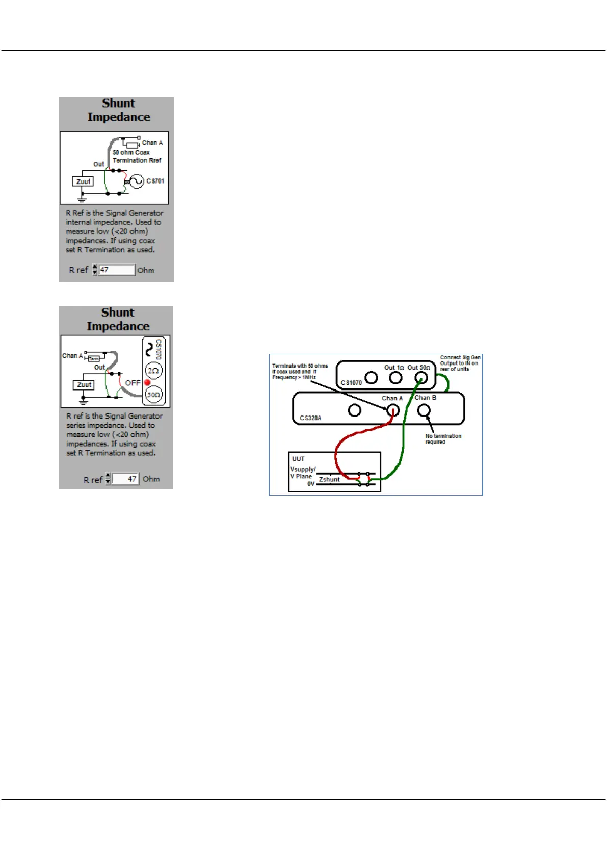
Shunt Impedance - used to measure low impedance (1 mOhm to 20
Ohm) values. Does not require a reference resistor. Use the Circuit as
shown - you must use a terminated coaxial cable connection to project a
50 ohm impedance to the board connection. Keep the coax pigtails as
short as possible. The CS1070, if available, allows impedance and phase
measurement with higher voltages and into powered up circuits with
voltages as high as 30V. If using just the CS700A or CS701 a maximum
circuit voltage of 3.3V applies. Impedance in Ohms or dBOhms. Good
for PCB impedance measurement with powered or unpowered power
planes.
For both the CS700A/701 and the CS1070 you must use the 50 ohm output
to ensure best matching to the coax at high frequencies. The CS1070 1R
output is not suitable due to mismatch.
Use the CS1070 to boost the signal generator output voltage. The CS1070
can output a signal over a voltage range of +30 /-18V. To measure shunt
impedance on a powered up Unit Under Test (UUT) make sure the CS1070
has power conected, and is disabled (red led on). The CS1070 power supply
should be at least 2 volts higher than the UUT voltage. Connect up the
system as below (with power turned off to the UUT).
Note that you need to make a 4 point measurement - the Channel A ground
and signal lines should be connected close to, but not on the signal
generator ground and signal lines. After connecting up the CS328A and
CS1070 to the UUT as above, configure the FRA control panel as follows:
Choose the Use CS1070 50 ohm signal generator option.
Power Led selected to Red - the CS1070 will be turned on by the
application.
Analysis Type
Set to Shunt Impedance. Shunt Impedance is used to meaure low
impedances from 1 mOhm up to about 20 Ohms. Impedance is plotted.
Auto Setup
Set Options/Auto Setup On to ensure that the signal generator offset is
correctly set.
Set Sig Gen Amp to give a good SNR, 1V is a suitable starting point. You
can use a Sweep Amplitude of Auto, and a Response V Goal of >3mV.
Make sure you set the Auto Amp Limit to less than the power supply
voltage.
The application automatically turns the CS1070 power on and off (assuming
you have the CS1070 link port connected to the CS3288A link port). If