v2.13 Cleverscope CS300 Reference Manual
©Cleverscope 2004-2018 www.cleverscope.com Page 107
needed you can independently control the CS1070 power enable state by
clicking on the Power LED . Green is enabled. Red is disabled.
Notes:
If the UUT is powered, the CS1070 output is automatically set to be a
sinking load, and the sine wave signal does not go above the UUT power
rail. If the UUT is not powered, the CS1070 will output a signal centered on
0V.
The Signal Generator amplitude is specified in V p-p.
17.5.1.3 Calibration
Calibration
Calibrate Probes
Calibrate CS1070 1R
Calibrate Fixture
You can improve the accuracy of the FRA system by calibrating the probes
and the fixture and by compensating for the Open Circuit Capacitance of
your test system. Calibration results are saved in your setup, and also in any
.apc results files. You can save a setup as a .apc file, and when you load the
file, you will use the calibration data captured earlier.
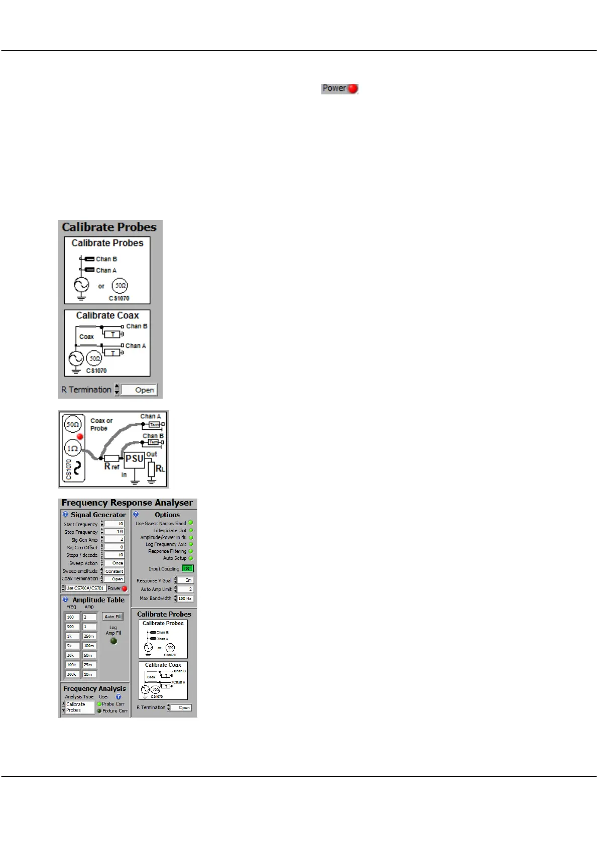
Probe Calibration (Short Circuit calibration) - also applies to CS1070 1R
To correct and calibrate Probe non-linearities connect the Sig Gen output to
the Channel A and Channel B probe tips, all together. Have no additional
impedance to ground (other than coaxial terminations). Connect all the
ground clips together. See the Calibrate Probes diagram.
If you are using a SMT fixture with 50 ohm terminated coax cables use a 0
ohm resistor in the fixture to set Zuut = 0. If you are using a Shunt
connected fixture, have nothing connected to the shunt connection.
Calibration automatically takes account of the number of termination
resistors. If you are calibrating the CS1070 1R, do not connect the PSU.
Select the Analysis Type to
Calibrate Probes
. Setup the Start and End
Frequency to capture the frequency range you are likely to be using. You
will get best results if you choose the same number of steps per decade (or
more) as you intend to use. Interpolation is used as necessary. A Sig Gen
Amp of 2V, and Scope Graph ranges of +/-1.5V will give good results. Click
Start Sweep, and the Probes or Fixture will be calibrated. Probe Correction is
applied when the Probe Corr LED control is on. The LED is dimmed when
there are no recorded correction values in the .apc file.
A typical probe calibration setup is shown to the left.
Calibrating the Open Circuit Capacitance
This is best done after a Probe Calibration. Setup your test jig as it will be,
but do not connect Zuut. Set the Analysis type to Capacitance/Inductance,
and the L-C Display to C - Resr. Set C Open to 0. Start a sweep, click Fit on