the Spectrum Display to show the Capacitance values. You will only be able
to measure this above about 10 kHz. Note the value - it is the open circuit
capacitance. Enter this value into the C Open field. A value of 1pF is entered
as 1p. If you run the sweep again the Capacitance graph should show
approximately 0 pF. Next do a fixture calibration for maximum accuracy.
Fixture Calibration (known impedance calibration)
Any test arrangement you use, for example scope probes or an SMT test
fixture will have additional parasitic resistance, capacitance and inductance
in the fixture and cables. We would like to de-embed these parasitics.
Use the Impedance Setup that you intend to use (Probe or coax, Circuit A, B
or C).
R cal replaces Zuut. By knowing Rcal, we can estimate the additional
parasitic elements, and compensate for them. Data is recorded in the .apc
file, so do a file Save As.. and save the setup for later use.
Select the Analysis Type to Calibrate Fixture. Select the Circuit you intend to
use. Type in the two known values R ref and R cal. R cal substitutes for
Zuut. Ensure the value you use is accurate. You can only use Fixture
Correction when the Circuit you used in calibration matches the circuit you
are using to test with. R ref and R cal should have low parasitic L and C.
To do the Fixture Calibration:
1. You must do a Probe Calibration before doing the Fixture Calibration,
and have Probe Corr on .
2. Find the Open Circuit Capacitance as explained above and enter it.
3. Set the Analysis Type to Calibrate Fixture.
4. Choose the correct measurement circuit. Set up R cal (Zuut) and R ref as
shown in the diagram, enter the values. Set the frequency range to be
same as used for Calibrate Probes. Use Narrow Band. Setup Scope
display to capture signal (+/-1.5V should do it). Set up Sig Gen
amplitude (2V should do it).
5. Click Start Sweep. The system will measure and display the R ref value
including parasitics. Make sure the Probe Corr LED is ON.
6. Do Save As.. and save a file name which reminds you of the fixture and
frequency range. This setup will save both the Probe and Fixture
calibration values.
7. Now set the Analysis Type back to what you wish to measure, (the
Fixture Corr LED will automatically have been turned on) and Start
Sweep as normal.
You can turn Fixture Correction on or off with the Fixture Corr control LED.
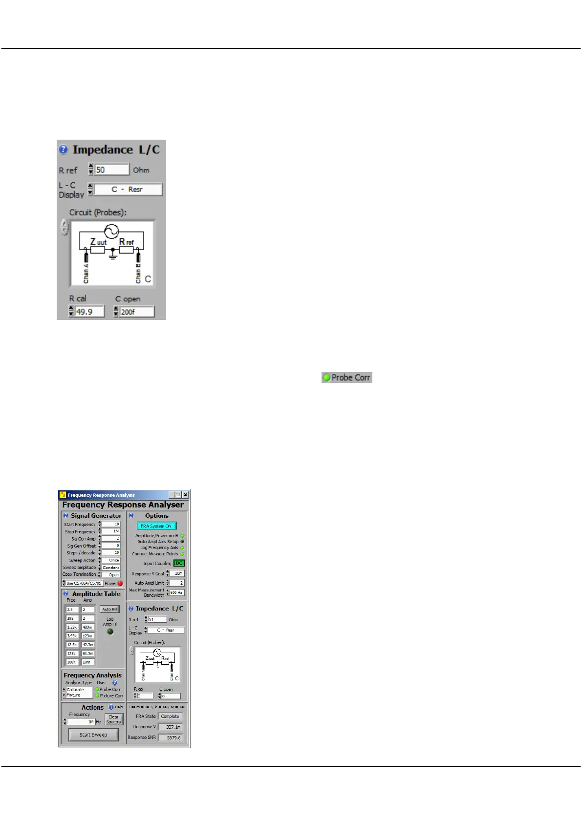
A typical probe based fixture correction is shown to the left. We are using
Circuit C. Zuut is replaced with 49.9 ohms (Rcal), R ref is measured with a
precision multimeter as 47.1 ohm. The open circuit capacitance was found
to be 200fF.