PSU Measurement Group
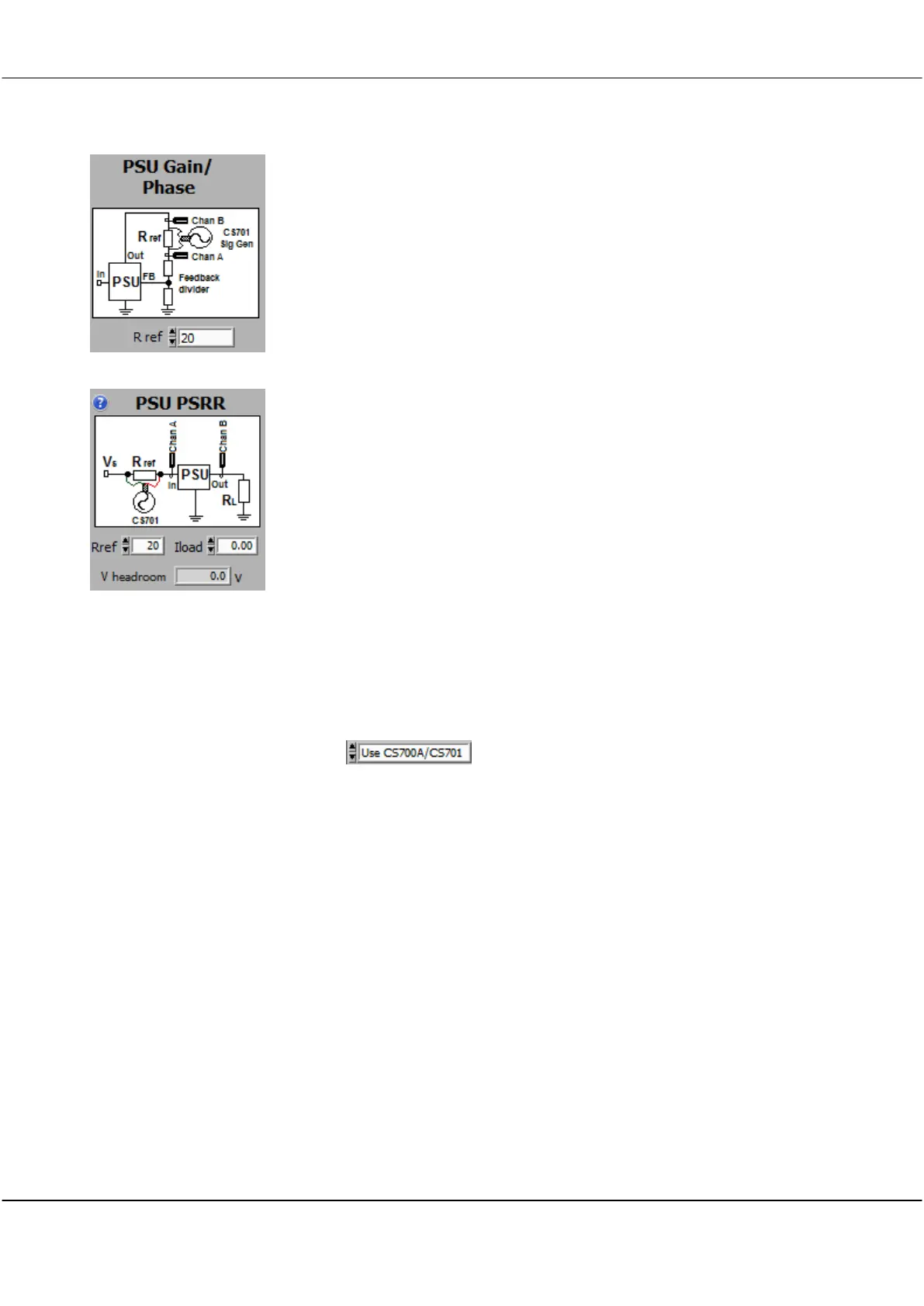
PSU Gain/Phase - used to measure the Gain/Phase of power supplies,
where the signal is injected across a resistor in the feedback path. Can
only be used with the CS701 or an isolated CS1070.
See the examples at the end of this section.
Rref is the value used to inject the signal across, which is in series with the
feedback chain. Useful values are 20 - 50 ohms.
PSU PSRR - used to measure the Power Supply Rejection Ratio of power
supplies. With a CS701 (NOT the CS700A) you inject across a resistor in
series with the power supply. With a CS1070, current (<1A) is provided
by the CS1070. The PSRR is the ratio of the input voltage perturbation
to the output response. It is a positive number expressed in dB.
Generally power supplies will have high PSRR at low frequencies
dropping off as frequency increases. To measure the PSRR of PSU alone,
make sure any input capacitors are the minimum required for stability.
Use the CS701 to measure the PSRR (Power Supply Rejection Ratio) of low
current (< 500 mA) regulators. A separate Power Supply sources Vs for the
test. The CS701 applies an AC voltage across a series resistor which is
sourcing current to the Unit Under Test (UUT) from Vs. This requires
isolation, and the CS700A cannot be used. Connect up the system as
shown in the system diagram. Rref is the series resistor across which the AC
signal is impressed. You need to make sure the separate power source
supplying Vs has an output voltage> Vin (psu) + V headroom.
After connecting up the CS328A and CS701 to the UUT as shown in the
system diagram, configure the FRA control panel as follows:
A CS701 is required. A CS700A cannot be used.
Rref
The series resistor across which the CS701 signal is applied. It is
preferable to connect the BNC shield to the Vs side of Rref. Suitable
values for Rref range from 5 ohms to 50 ohms. Make sure the voltage
drop across Rref does not exceed 2V. For example with 50 ohms, you
can source a maximum of 50 mA. With 5 ohms, you can source a
maximum of 500 mA. The CS701 signal is applied via a 50 ohm series
resistor, and so will be attenuated by Rref. With a 5 ohm Rref,
maximum impressed voltage is 630 mV p-p. With a 50 ohm series
resistor the maximum is 3.5 V p-p. The assumption is that the sourcing
supply is low impedance to reflect this impressed voltage to the UUT.
Iload
Estimate the load current based on the output voltage and load
resistance, or just measure it. The load value is used to estimate V
headroom.
Sig Gen Amp
Set the AC signal voltage used to excite the UUT input supply. This
should be set to the minimum needed to get a good Response SNR. You
can also set Sweep Amplitude to Auto. A target stimulus of 3mV is
suitable.