Cleverscope CS300 Reference Manual v2.11
Page 120 www.cleverscope.com ©Cleverscope 2004-2015
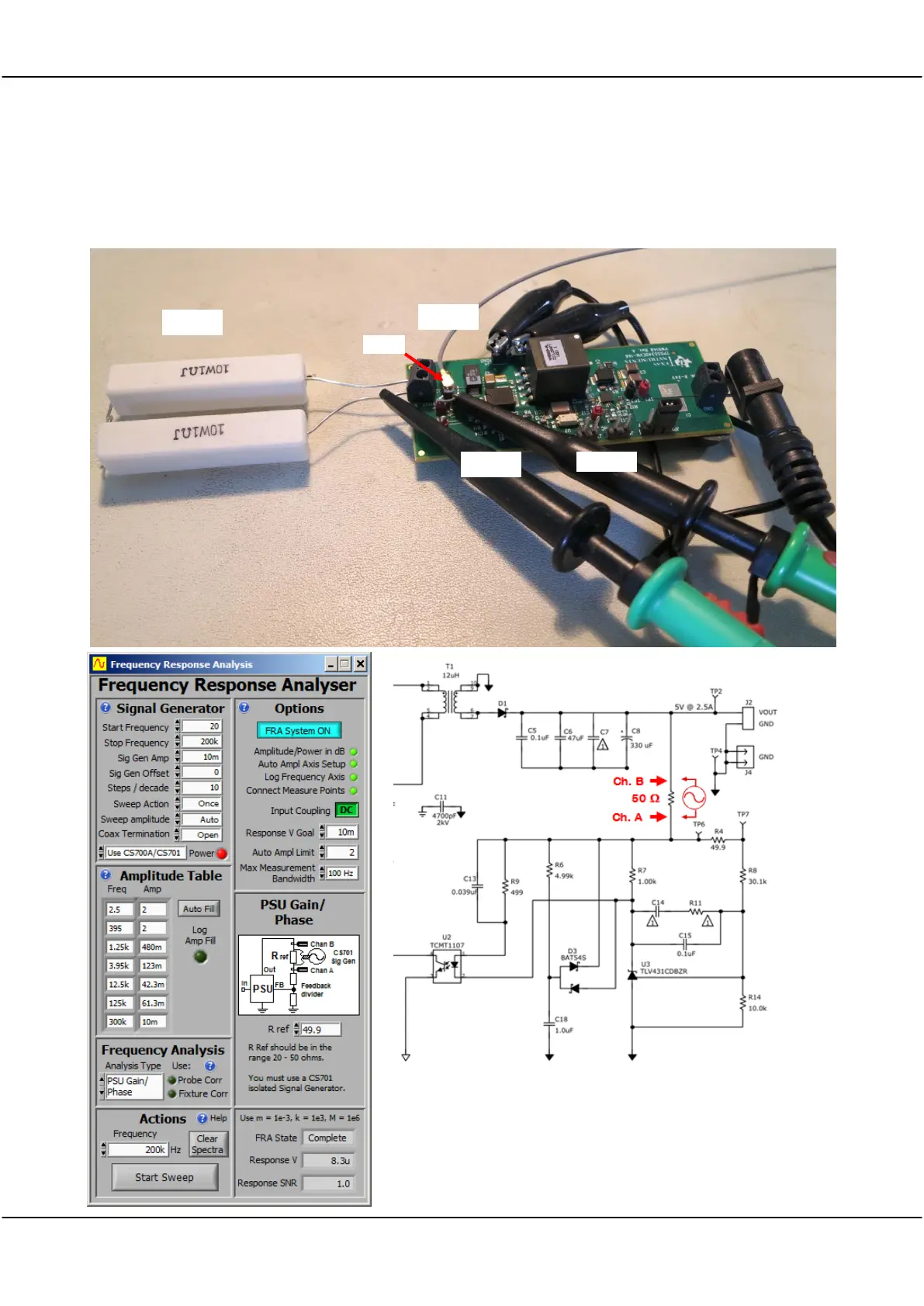
17.5.13 Measuring the Gain/Phase of a live switched mode power suppply
The CS701 Isolated Signal Generator is required for this. You cannot use the CS700A. If using the CS1070,
make sure it is driven by a CS701, and is fully isolated.
Probes are used for connection. We soldered a UFL socket onto TP6 to inject the signal. Chan A measures the
stimulus
, and Chan B measures the
response
.
The
TI EVM power supply voltage control loop part of the schematic is
shown. We have inserted a 50 ohm resistor between the output
and TP6, which is the start of the feedback attenuator chain. The
FRA setup covers a range of 20Hz to 200 kHz, and is set for Auto
Setup with auto amplitude.