v2.13 Cleverscope CS300 Reference Manual
©Cleverscope 2004-2018 www.cleverscope.com Page 119
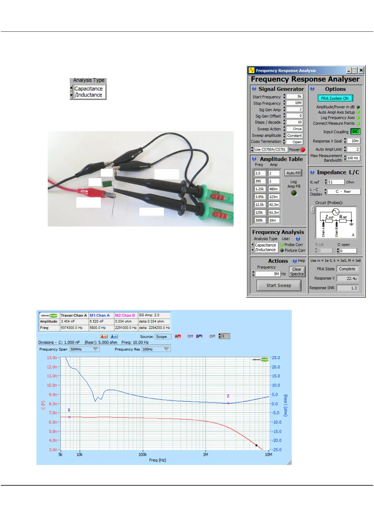
17.5.12 Measuring a Capacitor, Inductor or Resistor
Steps:
1. Choose
2. We are measuring a 6.8 nF leaded mylar capacitor, using Circuit A,
over a frequency range of 1kHz to 5 MHz. Setup the FRA control
panel as shown.
3. Connect up the components:
Keep the lead length between the components and probes short to
minimize lead inductance.
4. Click
Start Sweep
.
The Scope Display will be automatically setup, and the Spectrum display
shows the plot below. You can adjust the view using the axis tools (hover
over a control to see help), or use the Ctrl / Arrow keys to zoom in and out
on the tracer. The tracer, in black, shows values at that point (3.4 nF at
6.37MHz - half capacitance). The markers (1/blue and 2/red) are placed by
clicking '1' and '2'. Tab between channels. Here we see the 6.8nF capacitor is actually 6.5 nF (-4.4%), and falls
off at about
1.5 MHz. ESR
is 34m Ohms
at the self
resonant
frequency.
The self
resonant
frequency is
about 2.5
MHz.