Cleverscope CS300 Reference Manual v2.11
Page 118 www.cleverscope.com ©Cleverscope 2004-2015
17.5.10 Example FRA Setups
These setups should help you in setting up the Cleverscope to make various FRA measurements.
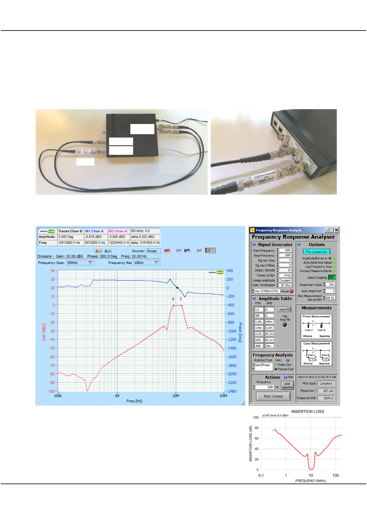
17.5.11 Measuring the Gain/Phase of a Minicircuits 10.7 MHz Band Pass Filter
The Minicircuits filter is designed to be driven by a 50 ohm source with a 50 ohm load. To do this, we used a
BNC splitter to drive two 10dB attenuators, with equal length coax then driving the filter terminated with 50
ohms. This is the setup:
The filter is shown plugged into channel B, with 50 ohm terminators on the two channels.
Here is the response we measure, the markers show the band pass frequencies to be 9.07 - 12.23 MHz:
The Stop Band amplitude is -80 dB or so.
The Mini-Circuits insertion loss in the data sheet is shown to the right.
It is inverted with respect to the Gain/Phase. To plot insertion loss with the
FRA, reverse the A and B channels.
10 dB
attenuators to
ensure 50
ohm driven
impedance