v2.13 Cleverscope CS300 Reference Manual
©Cleverscope 2004-2018 www.cleverscope.com Page 25
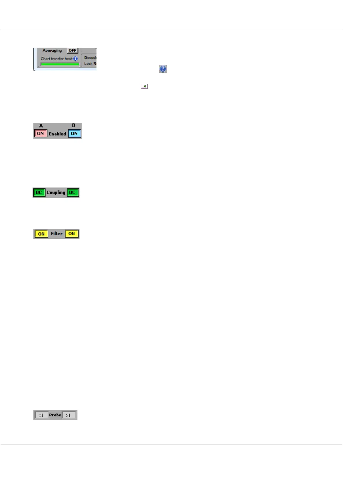
During charting, the bottom left corner of the Control Panel changes to show
Chart transfer health.
Click the help icon ( ) for more information.
Toggle Automatic Scrolling
Click Chart ( ) to toggle automatic scrolling of the on the Scope Display graph.
4.2.4 Enabled
Click ON button to toggle channels ON or OFF to determine whether signals are
displayed or not. Un-displayed signals are still acquired, and can be displayed by turning
the channel ON.
Controls are independent of each other.
4.2.5 Coupling
Click button to toggle channels to DC Coupled or AC Coupled.
Controls are independent of each other.
4.2.6 Filter
Click button to toggle channels to use a 20 MHz pre-filter and/or a moving average filter
(with time constants from 40ns to 1.28us) in the incoming signal stream.
Filter Setup
20Mhz
Pre Filter
Corner Frequency
Decimation
To setup which filter is used see the section 5.3.6 Acquisition settings.
The 20 MHz pre-filter employs a 5
th
order low pass anti-aliasing filters on each channel to
prevent high frequency out-of-band signals from aliasing back into the displayed signal
graph.
The unit always samples simultaneously for both channels at 100 M samples/s.
Corner frequency of the anti-aliasing filters is 20 MHz.
If the effective sample rate (e.g. 1MSPS when sampling 2 seconds with 2 frames on a 4M
Cleverscope) is lower than the actual sample rate (100 MSPS), then decimation is used to
achieve the effective sample rate. If the Filter button is on, then equally spaced sample
decimation is used, and intervening samples are lost (though they may have been filtered).
If the Filter button is off then peak-captured decimation is used, where both the highest
and lowest values of the intervening sample set are captured. This ensures that short
duration signals are visible. The sample set is itself decimated according to the Display
Method.
4.2.7 Probe
Click in the field to select from a dropdown list to set Probe attenuation for each channel to
match the attenuation switch settings of the connected probe.
Options are x1, x10, x100, x1k, x20, x50 or x200.