Cleverscope CS300 Reference Manual v2.11
Page 50 www.cleverscope.com ©Cleverscope 2004-2015
Cleverscope devices found on LAN display zone
The panel will report values for all connected CAU's. Click on a CAU line to select it. Each CAU has an entry for
the following:
The current CAU IP address (might be assigned by DHCP or manual)
The Gateway IP address used (when connecting outside a LAN).
The TCP Port used for TCP transactions.
States if the CAU is using DHCP or static addressing
Shows the CAU as available or not. If not, it is probably being used by
another Cleverscope application.
The total time the CAU has been on.
5.3.8 Acquirer Scaling [Settings Menu]
Acquirer Scaling
Straight line XY Plot
Pt. 1 and Pt. 2
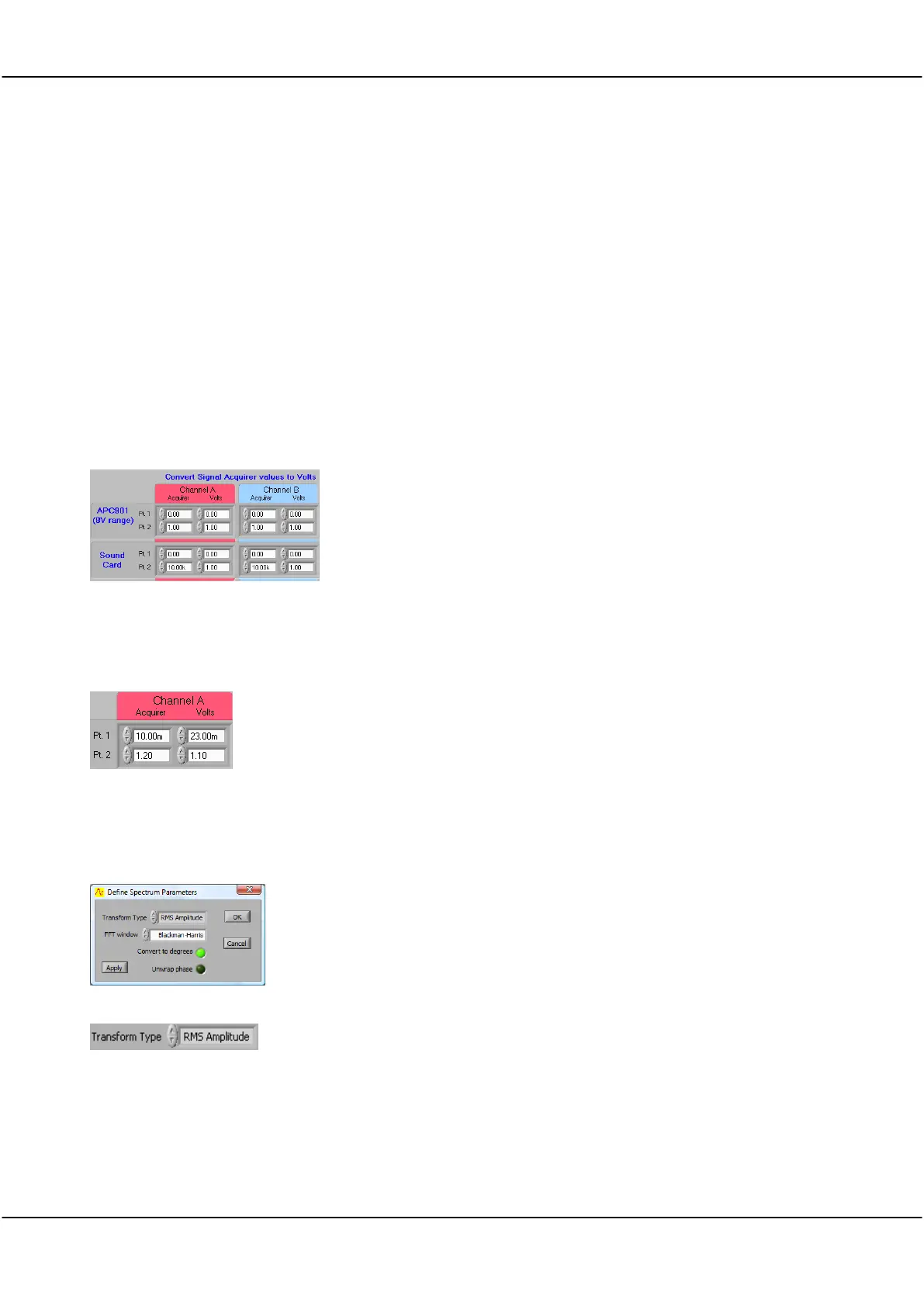
The Convert Signal Acquirer values to volts zone defines scaling and
offsets to be applied to measurements made by the Strobes hardware
(901 and 901A) and soundcards to compensate for any difference
between volts as read by the acquirer and any associated input circuitry
and the actual volts at the input.
An X/Y plot showing the linear relationship between the actual volts at
the input and the measurement in volts as made by the acquirer must
be a straight line.
Define the X/Y straight line, and therefore define the scaling and offset
to ensure that the volts as read in Cleverscope are the same as the
actual volts present at the input.
For example, if by measurement the acquirer reads 10mV for a real 23
mV signal and 1.2 Volts for a real 1.1 Volt signal, then Pt. 1 and Pt. 2
should be as shown on the right.
5.3.9 Spectrum (Ctrl+F) [Settings Menu]
Define Spectrum Parameters
You can select the type of Fourier transform to be applied, the windowing
technique to be used, whether phase information is plotted in degrees or
radians, and whether Phase should be plotted between -180 and 180
degrees or 0 to 360 degrees.
Click on the arrows or in the field to select from the dropdown list.
Options are: RMS Amplitude, Power, Power Density, or Gain/Phase.
Returns the magnitude of a signal in volts.
RMS amplitude is the most common type of Fourier transform. The RMS
(root mean square) voltage for each frequency bin is displayed.
This value is equivalent to a continuous sinusoid at the bin frequency with
RMS amplitude equal to that displayed. The RMS value of a sinusoid is a