ComNav Commander P2 & P2VS Installation & Operation Advanced Operations
Document PN 29010074 V4.1 - 156 -
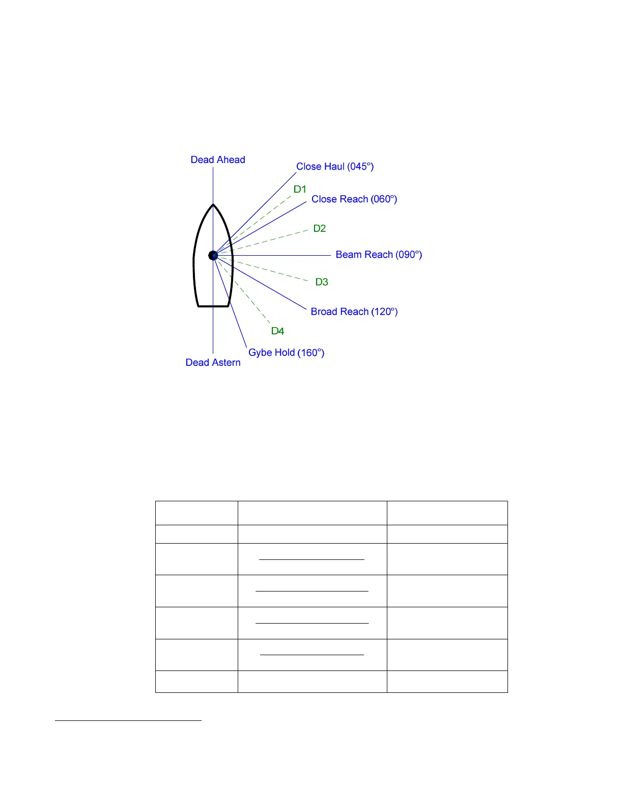
Boundaries of the Points of Sail
The boundaries between the Points of Sail are used in deciding which Point to change the
Commanded Wind Angle to, when making a turn. The Point chosen is the one between the
boundaries that the actual wind angle falls in.
To show how the boundaries are determined, look at the following diagram
41
.
Figure 101 – Points of Sail
Note: when the WIND-Points mode is entered, the Commanded Wind Angle will be
the actual wind angle, even if it is not one of the Points of Sail. But, if you then
turn the
C
C
O
O
U
U
R
R
S
S
E
E
C
C
H
H
A
A
N
N
G
G
E
E knob, the Commanded Angle will change to the Point of
Sail which is closest to the actual wind angle.
Each of the boundaries (labelled “D1”, “D2”, etc., in the figure above) is half-way between the
surrounding Points of Sail. Since the angles of the Points of Sail can be changed, in the
Wind menu, the angle of the D1 – D4 boundaries can change too (Dead Ahead & Astern are
also boundaries, but have fixed values).
Divider Calculated By Default Angle
Dead Ahead — 000°
D1
2
Reach CloseHaul Close +
052.5°
D2
2
Reach BeamReach Close +
075°
D3
2
Reach BroadReach Beam +
105°
D4
2
Hold GybeReach Broad +
140°
Dead Astern — 180°
Table 8 – Boundaries Between Points of Sail
41
The angle values shown in the diagram for the Points are all the default definition values; if you change any (see page
156), then the angle(s) will be the changed value(s).