ComNav Commander P2 & P2VS Installation & Operation System Overview
Document PN 29010074 V4.1 - 26 -
System Overview
This chapter gives a brief description of the major elements of the Commander P2 Advanced
Autopilot System, their functions, and their relationships to each other.
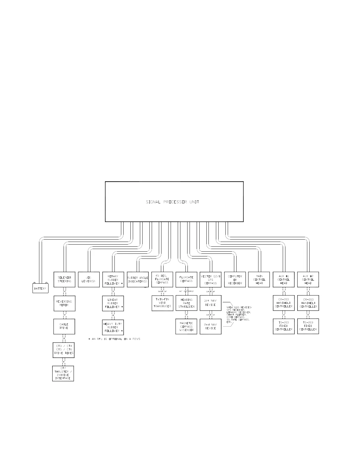
Below is a block diagram of a typical example of the Commander P2 system, showing the
interconnections between the elements of the system:
•
The Signal Processor Unit (SPU)
•
The Main Control Head
•
A Compass or other Heading Sensor
•
Solenoid(s), Reversing Motor, or Cable Drive, which move the Rudder
•
The Rudder Follower Unit (optional on a P2VS)
•
Optional Auxiliary Control Head(s) & Remote Controls
•
Various optional accessories & external equipment
•
Other Navigation equipment
Figure 3 – Commander P2 System Block Diagram