ComNav Commander P2 & P2VS Installation & Operation Installation
Document PN 29010074 V4.1 - 60 -
Wiring the System
Once everything is securely mounted, you can begin wiring the various components of the
system, one at a time.
ComNav strongly recommends that ABYC wiring standards, or the equivalent
for your locale, be followed.
Signal Processor Unit
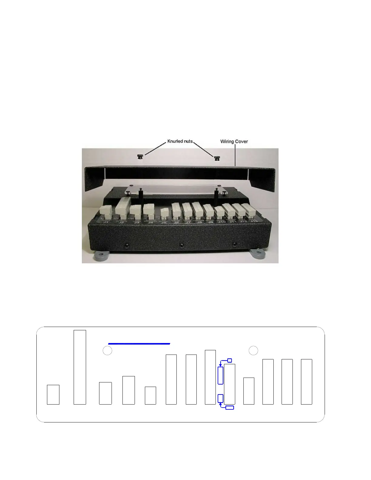
Start by removing the Wiring Cover from the SPU. It is held in place by two knurled plastic
nuts (see Figure 34).
Set the cover & nuts aside – they will be re-installed once all the wiring of the SPU is
complete.
Figure 34 – Removal of the SPU Wiring Cover
Connectors on the SPU
With the wiring cover off, all the SPU’s connectors are visible & accessible.
Each connector is a pin receptacle, with the pins sized according to how much current will be
carried – bigger pins for higher current. Each pin has a signal name, rather than a number, to
make it easier to match wires with pins (see connector label, below).
IN
J9
OUT
NAV I/O
C
U
T
O
U
T
P SERIES SPU
CHASSIS
M1 / PORT
J1
INPUT
BATTERY
-
B
B
+
STBD
OUT
OUTPUTS
DRIVE
J2
LEVER
J3
JOG
SW'D B+
PWR
GND
SW'D B-
GND
PORT
RUD.SIG
M2 / STBD
RUD.RET
CA
HI SPD
SSM
I/O
J6
MISC.
V+
+
+5V
OUTPUT
J4
FOLLOWER
RUDDER
J5
RAI
-
GND
SIG
GND
DIO2
AN OUT 1
DIO1
GND
AN OUT 2
DIO3
WORK
1 PPS
SIN
B
V+
COMPASS
I'FACE
THRUST
J7 J8
COS
V+
WA
WB
REF
EX2
EX1
GD
BP
GND
BPM
BS
SS
BSM
SP
SPM
1B
GD
A
1A
CH
2B
2A
ComNav
CB
J12
AUX 1
V+V+
SH
NETWORK
J10
ComNav
J11
HEAD
CONTROL
CL
DO
DI
ON
V+
GD
SS
FR
PS-
PS+
C+
C-
FR
SS
GD
V+
ON
DO
DI
CL
V+
J13
AUX 2
FR
SS
GD
V+
ON
DI
DO
CL
Figure 35 – SPU Connector Wiring Label