ComNav Commander P2 & P2VS Installation & Operation Installation
Document PN 29010074 V4.1 - 64 -
Input & Output Connections
Control Head
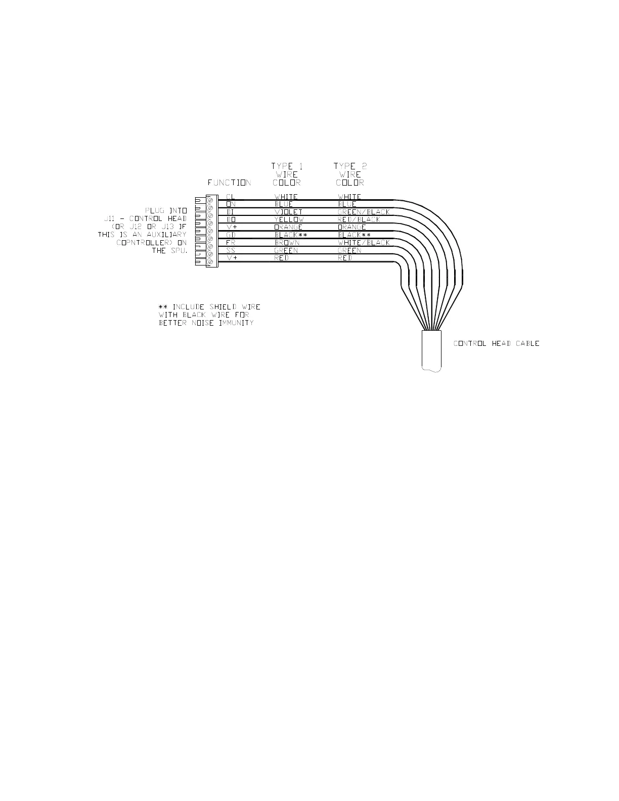
Two types of control cable are used in manufacturing Commander P2 systems. The only
difference between them is the colour-coding of the wires. Wire the cable from the main
Control Head onto the nine-position plug-in connector according to the following diagram:
Figure 39 – Wiring Connections for Control Head, Handheld Remotes, and Fixed Remotes
Plug the nine-position plug connector into the SPU receptacle labelled
J11 - CONTROL HEAD
.
Auxiliary Controller(s)
All Control Heads, Handheld Remotes, and Fixed Remotes designed to work with the
Commander P2 utilize the same wiring diagram as the Main Control Head (see Figure 39,
above). The only difference is that these devices are plugged into the receptacles
J12 - AUX
1
or
J13 - AUX 2
instead of
J11 - CONTROL HEAD
.
Note: Auxiliary Head Power On/Off
The Commander P2 SPU is shipped from the factory configured so that power
can only be turned on or off from the Main Control Head. The Main Control Head
is designated as the Head which is plugged into the SPU receptacle labelled
J11 - Control Head.
However, the system can also be configured so that it can be turned on or off by
any Control Head plugged into the receptacles J12 - Aux 1 or J13 - Aux 2 (note:
power cannot be turned on from CR-203 or TS-203 Remotes). If reconfiguration
is desired, follow the instructions for enabling Auxiliary Head / Remote Power On
(see page 199).