ComNav Commander P2 & P2VS Installation & Operation Installation
Document PN 29010074 V4.1 - 77 -
Some installations require separate monitoring for power failures. This can be accomplished
with the following circuit, which utilizes two relays. The coil voltage of the relays should
match the supply voltage for the autopilot. The Alarm Supply, which must be a separate,
dedicated supply from the autopilot supply, should match the voltage of the alarm.
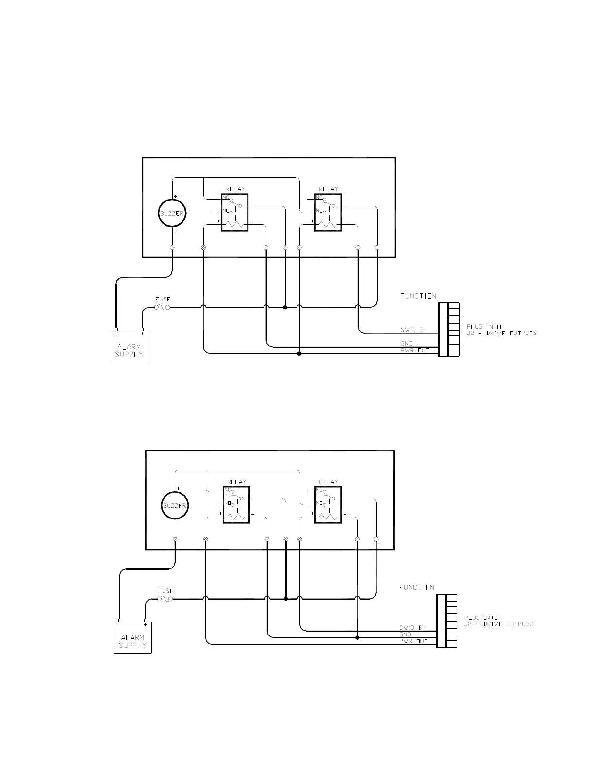
This is the circuit for using Switched B- as the alarm output:
Figure 60 – External Alarm, SW'D B- Output with Power Fail Option
This is the alternative circuit, using Switched B+ as the alarm output:
Figure 61 – External Alarm, SW'D B+ Output with Power Fail Option