ComNav Commander P2 & P2VS Installation & Operation Installation
Document PN 29010074 V4.1 - 63 -
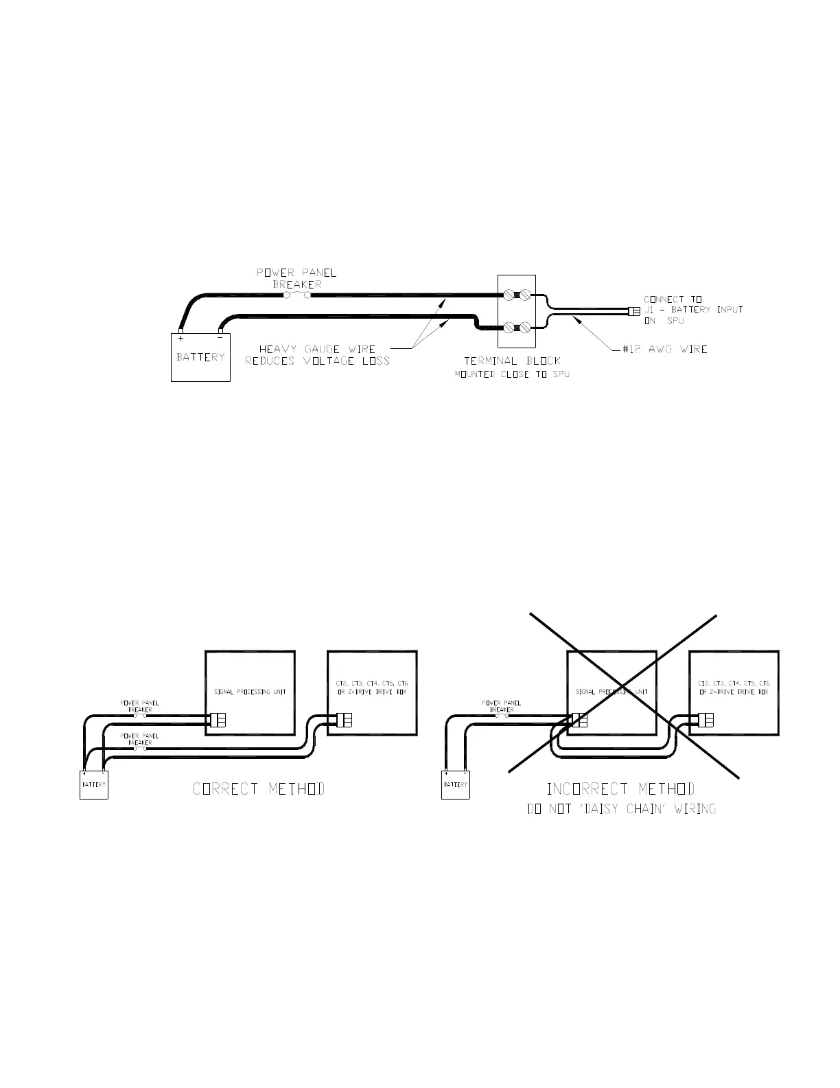
Power Supply Extension
If the SPU is mounted a long distance from the ship’s breaker panel, it is recommended that
heavy gauge wire (#8 AWG or larger) be routed between the breaker panel and a suitable
terminal block, which is mounted in close proximity to the SPU. A short length of #12 AWG
wire can then be used between the terminal block and the SPU. This minimizes voltage drop
between the breaker panel and the SPU. The terminal block is needed, in this situation,
because the wire openings in the plug for J1 can accept a maximum wire size of 12 AWG, so
wire larger than that can not be directly connected to J1.
Figure 37 – Reducing Supply Voltage Losses
You may also want to use the same heavy-gauge extension wire technique for the Rudder
Drive output wiring, if the SPU is located a long ways from the Rudder solenoids, valves,
actuator, motor, etc. (see
Drive Outputs
on page 71).
Drive Box Power Supply
If your autopilot system utilizes one of ComNav’s CT Drive Boxes, it should be wired back to
the breaker or fuse separately from the rest of the autopilot system.
Do
NOT
ever “daisy-chain” power wiring!
The following diagram shows the proper method when using a CT Drive Box:
Figure 38 – Typical Battery Connection to Drive Boxes