ComNav Commander P2 & P2VS Installation & Operation Installation
Document PN 29010074 V4.1 - 67 -
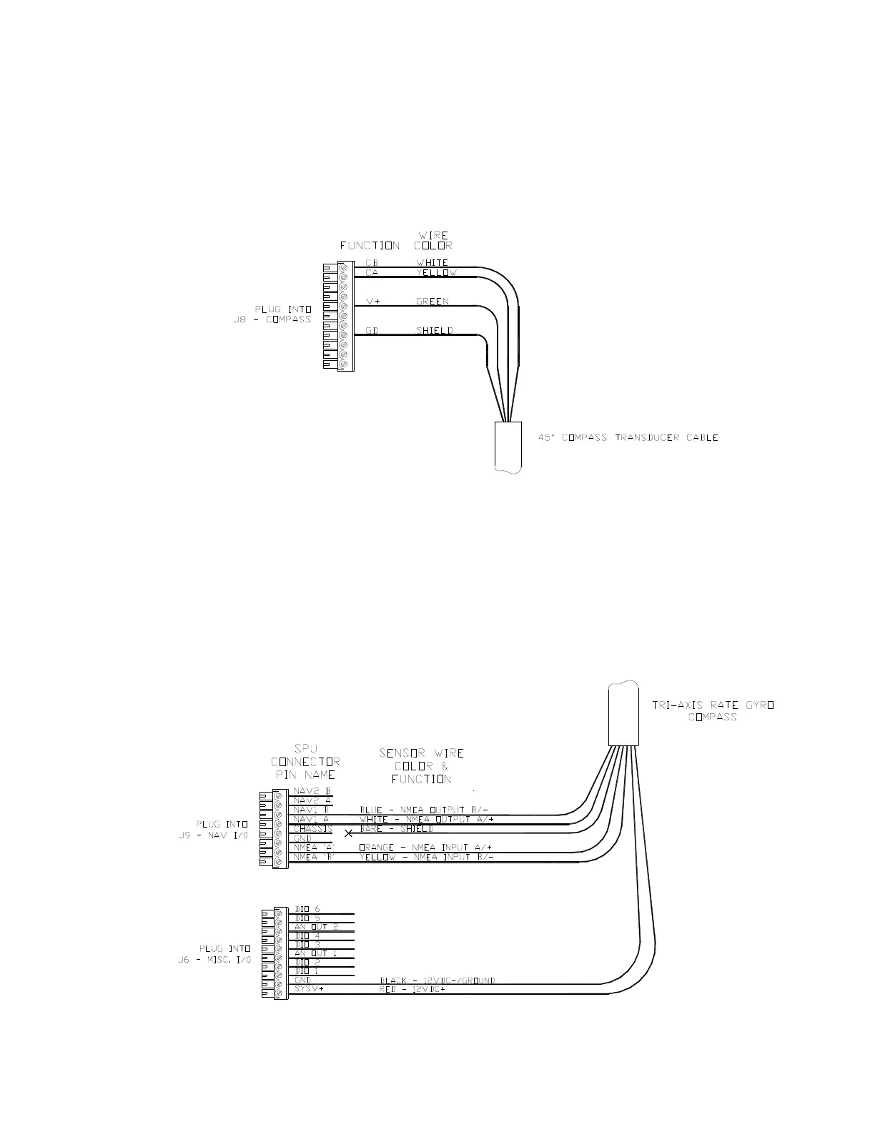
If you have a 45° Compass Transducer, it is also connected to
J8,
as per the following
diagram.
Note: more than one wire (in the standard cables) will fit into the V+ and GD
(Ground) connections, so you can connect a 45° Compass and a Fluxgate
Compass (or HRS) at the same time. You may then select either as the
“Compass Source” (see page 117) at any time during operation.
Figure 42 – Wiring Connections for 45° Compass Transducer
If you have a Tri-Axis Rate Gyro Compass, it is connected through the J9 and J6 (for power
supply), as per the following diagram.
Note: you only need to connect signal wires to NMEA A and NMEA B during the
compass setup for calibration purposes. When the calibration is done, the signal
wires to NMEA A and NMEA B can be disconnected so that the NMEA port may
be used for other serial data connections. (Ensure that disconnected signal wires
must be properly isolated and taped to prevent electrical damage)
Figure 43 – Wiring Connections for Tri-Axis Rate Gyro Compass