109 of 282
M-SV-001-EN Rev. G
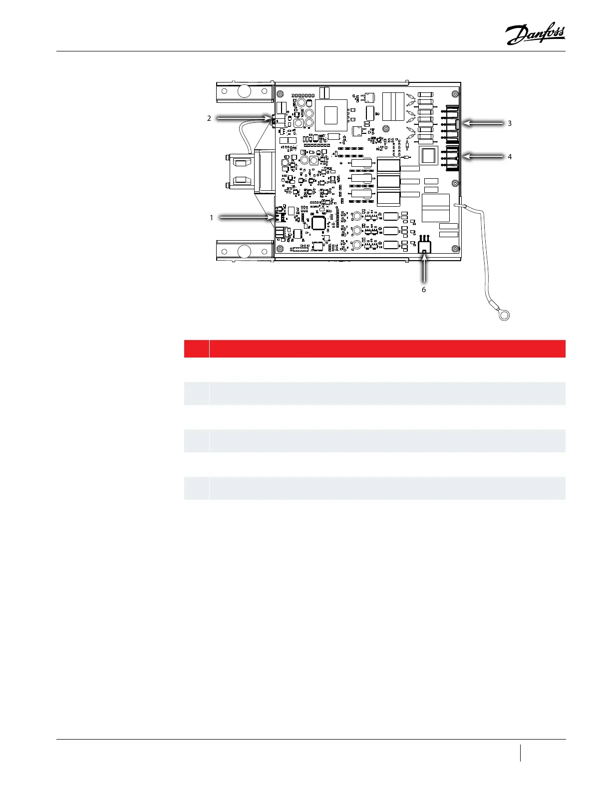
Figure 4-99 Open-Top Soft Start Connections
Table 4-24 Open-Top Soft Start Connection Identification
No. Component
1 J7: Soft Start Temperature Sensor connector
2 J3: Thermostatic Fan Control connector
3 J1: AC Inputs
4 J8: DC Link
5 Ground
6 J2: SCR Gate Signal connector
4.15.2 Soft Start Verification
4.15.2.1 Verifying Soft Start Voltages
1. Before verifying Soft Start voltages, ensure that the correct 3-phase main AC voltage is present
at the Mains Input terminals.
2. Using the DC bus test harness (refer to "1.10 DC Bus Test Harness Installation and Removal" on
page 22) with power applied to the compressor, verify that the expected DC bus voltage is
present for the application. Refer to "Table 1-3 Expected DC Bus Voltage" on page 25.
• No DC voltage may indicate that the Soft Start is not controlling the SCRs
3. Using the DC bus test harness with power applied to the compressor, verify that the 15VAC
to the DC-DC converter is present. Output can range from 12 – 25VAC, depending on primary
input voltage. (Closed-Top Soft Starts only)
• No 15VAC may indicate an open F2 or F5 fuse for revision "S" and "T" Closed-Top Soft Starts
• If the 15VAC supply is not present at start-up, the DC-DC converter will not function
1
2
3
4
5
6

 Loading...


