80 of 282 M-SV-001-EN Rev. G
4.10 IGV
The IGV assembly consists of movable vanes and a motor. The IGV assembly is a variable-angle guiding
device that is used to control the capacity at low-load conditions. The IGV position can vary between
approximately 0% (closed/perpendicular to flow) and 100% (open/parallel to flow). The vane angle is
determined by the BMCC and controlled by the Serial Driver. The Serial Driver, in turn, uses +15VDC to
control the IGV stepper motor.
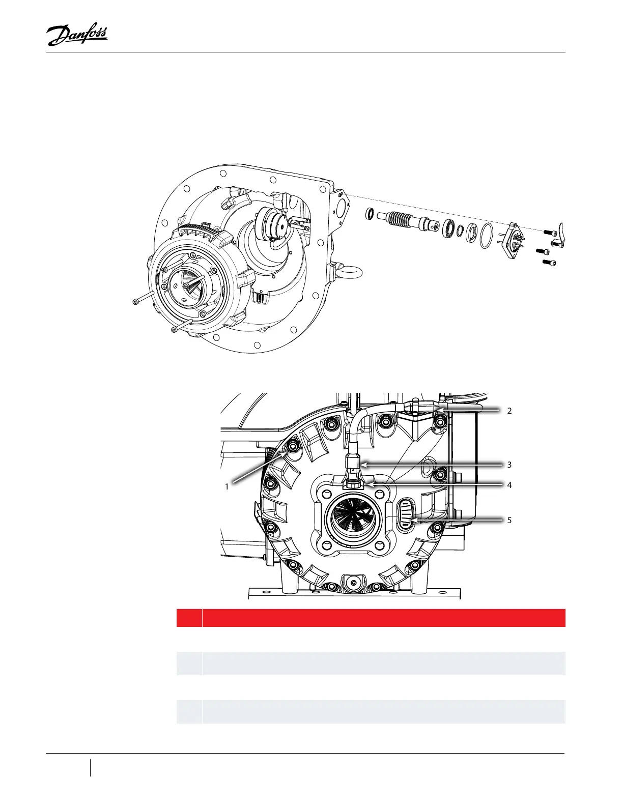
Figure 4-41 IGV Assembly
4.10.1 IGV Connections
Refer to "Figure 4-42 IGV Connections" for the location of the IGV connections.
Figure 4-42 IGV Connections
Table 4-14 IGV Components
2
1
3
4
5
No. Component
1 The IGV assembly is bolted to the compressor housing.
2 The compressor controller cable is held to the IGV Motor feed through by the cable clip.
3 The compressor controller cable continues on to the suction pressure/temperature sensor.
4 The suction pressure/temperature sensor is connected to the IGV Housing.
5 IGV Position Indicator.

 Loading...


