31 of 282
M-SV-001-EN Rev. G
Chapter 2.0 Compressor Fundamentals
Compressor operation begins with a demand signal applied to the compressor. The startup sequence
is configurable in the startup settings. See the OEM Programming Manual for further details.
2.1 Main Fluid Path
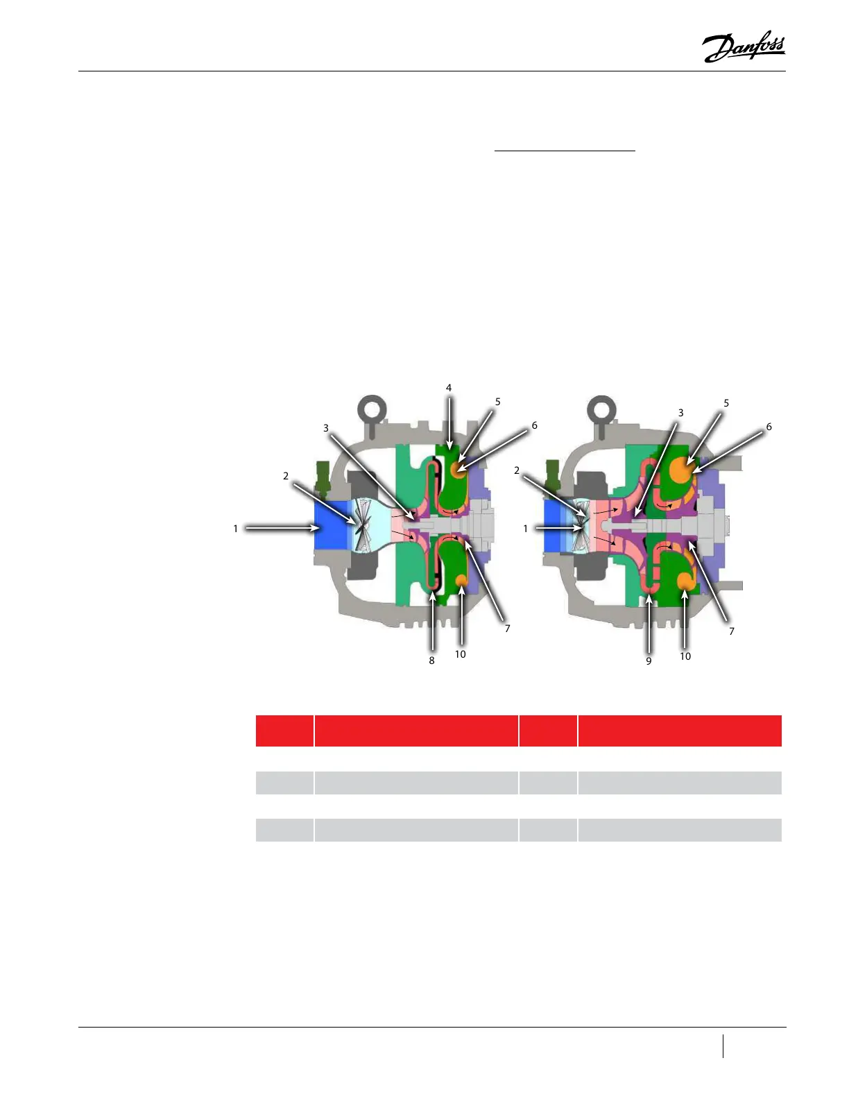
The compressor is a two-stage centrifugal type compressor utilizing variable speed as the principle
means of capacity control with inlet guide vanes (IGVs) assisting when required. Refrigerant enters
the first stage suction side of the compressor as a low-pressure, low-temperature, superheated
vapor. It then passes through variable IGVs that assist compressor control at part-load conditions.
Both impellers are mounted on a common shaft. Vapor passes through the first stage impeller where
velocity energy is added to the refrigerant. This is converted to an intermediate pressure in the first
stage volute. Vapor then enters the second stage impeller through a diffuser. In the second stage,
impeller velocity energy is again added to the refrigerant and converted to the final discharge pressure
in the discharge diffuser and volute. From the second stage impeller, refrigerant passes as a high
pressure, superheated vapor to the system discharge line.
Figure 2-1 Compressor Fluid Paths
Table 2-1 Compressor Fluid Paths
2.2 Motor and Power Electronics Cooling
Liquid refrigerant, having at least 2⁰C (Kelvin)/ 3.6°F (Rankine) sub-cooling at connection point, must
be piped to the compressor cooling inlet connection. This connection is a 1/2 inch O-ring face seal
(ORFS) connection with a built-in strainer. Refer to "Figure 2-2 Cooling Inlet Adapter" for an example of
the cooling inlet adapter.
1 1
2
2
3
3
4
5
5
6
6
7
7
10
10
8
9
No. Component No. Component
1 Low Pressure/Low Temperature Gas 6 High-Pressure/High Temperature Gas
2 Inlet Guide Vanes (IGVs) 7 Second-Stage Impeller
3 First-Stage Impeller 8 Vaned Diffuser
4 Volute Assembly 9 Vaneless Diffuser
5 Discharge Port 10 De-Swirl Vanes

 Loading...


