210 of 282 M-SV-001-EN Rev. G
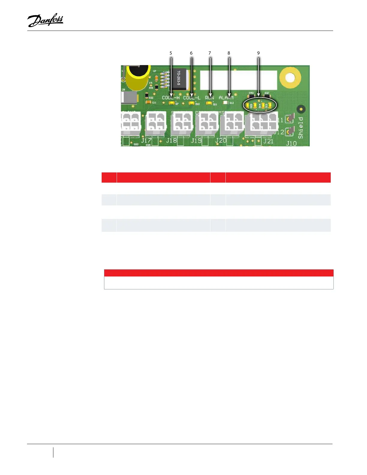
Figure 4-268 Backplane LED Locations - Right Side
Table 4-42 Backplane LED Locations
4.26.2.2 Backplane Verification
NOTE
The test-point LEDs are ON if any voltage is present. The test points must be measured to determine the actual voltage.
1. Remove the Service Side Cover. Refer to "4.2.3.1 Service Side Cover Removal and Installation"
on page 58.
2. With main power on, using a multimeter set for DC voltage measurements, place the
multimeter leads in the Backplane test points as defined in "Table 4-43 Backplane Test Point
Values" on page 211. Refer to "Figure 4-266 Backplane Test Points" on page 209. The results
should be within the voltage range specified in the table.
3. Isolate compressor power.
4. Unplug connectors J4 and J24 from the Backplane.
5. Using a multimeter set for resistance measurements, place the multimeter leads in the
Backplane test points as defined in "Table 4-43 Backplane Test Point Values" on page 211.
See "Figure 4-266 Backplane Test Points" on page 209. The results should be greater than the
resistance specified in the table.
6. If one of the test points does not output the expected voltage and the HV+ and +24V test
points output the correct voltage, remove the Serial Driver, BMCC, and PWM.
7. Plug connectors J4 and J24 to the Backplane.
8. Repeat Step 2. If the voltages are as expected, the Backplane is functioning correctly and
determine the cause of the energy drain.
5 6 7
98
No. Component No. Component
1 D2: +17 VDC 6 D10: Cool-L power to solenoid
2 D1: +5VDC 7 D11: Run contact is closed when on
3 D6: + 15 VDC 8
D12: Compressor Status: Red indicates alarm or
reset, Green indicates normal
4 D9: + 24 VDC 9
D13-D16: IGV Stepper Motor Indicator; flicker when
operating
5 D7: Cool-H power to solenoid present

 Loading...


