148 of 282 M-SV-001-EN Rev. G
4.19.3.5 SCR Installation - TTS/TGS/TTH/TGH (Except TTS300/TGS230)
1. Ensure that no residue remains on the contact surfaces of SCR Cooling Manifold.
2. If the SCRs are to be reused, inspect them to ensure there is enough thermal paste on the
contact surface. If they require additional thermal paste, take an SCR and spread a thin and
uniform coat of Dow Corning Silicone Heat Sink paste (or equivalent) entirely over the bottom
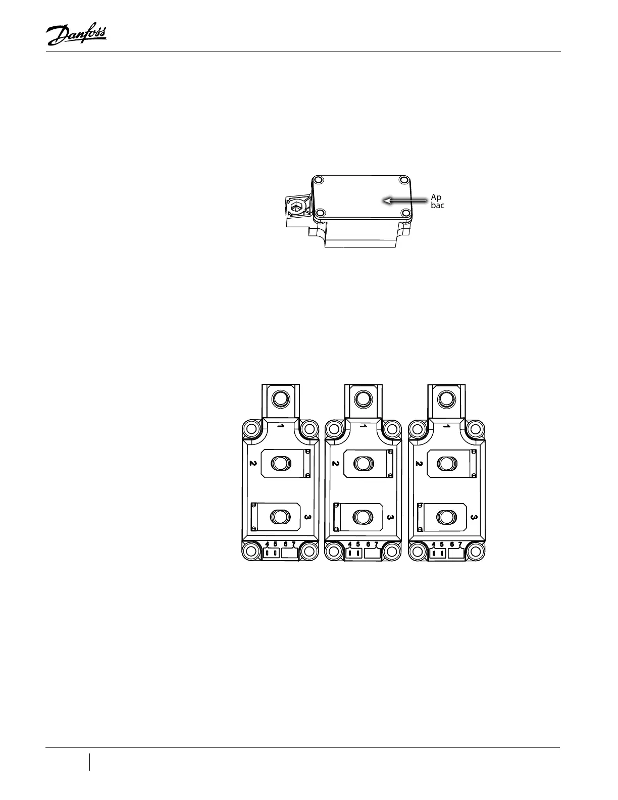
of each SCR surface. Refer to "Figure 4-169 SCR Thermal Paste Application - TTS/TGS/TTH/TGH
(Except TTS300/TGS230)".
Figure 4-169 SCR Thermal Paste Application - TTS/TGS/TTH/TGH (Except TTS300/TGS230)
3. Install the three (3) SCRs.
a. For Revision F and earlier compressors, finger-tighten the 12 M6x16 fasteners, then
tighten in a crisscross pattern in two (2) stages. Refer to "Figure 4-170 SCR Torque
Sequence - TTS/TGS/TTH/TGH Rev. F and Earlier (Except TTS300/TGS230)".
• Stage 1: Tighten to 2 Nm (18 in.lb.)
• Stage 2: Tighten to a final torque of 5 Nm (44 in.lb.)
b. For Revision H compressors, tighten the six (6) M6x16 fasteners to 5 Nm (44 in.lb).
Figure 4-170 SCR Torque Sequence - TTS/TGS/TTH/TGH Rev. F and Earlier (Except TTS300/TGS230)
4. Position the DC Bus Bar and Capacitor Assembly into place.
5. Loosely install the Snubber Capacitors to the Inverter noting the leg orientation.
6. Loosely install the DC Bus Bar and Capacitor Assembly to the SCRs.
7. Starting from the Capacitor side, torque the Snubber Capacitors to 7 Nm (62 in.lb.).
8. Torque the DC Bus Bar and Capacitor Assembly to SCR fasteners to 9 Nm (80 in.lb).
9. Place the capacitor membrane foam-side up, underneath the main compressor housing and
then Install the nylon nuts to the base of the DC Capacitor Bus Bar Assembly, torque to 5 Nm
(62 in.lb.).
10. Install the AC mains input terminals and bus bars.
11. Install the mains input cables to the Terminal Block and torque to 21 Nm (15 ft.lb.).
12. Install the Soft Start. Refer to "4.15.3 Soft Start Removal and Installation" on page 112.
Four Hole Mount Shown
Apply paste to
back of SCR
1
7
2
8 3
9
4
10
5
12
6
11

 Loading...


