76 of 282 M-SV-001-EN Rev. G
4.7.4.2 Solenoid and Actuator Installation
1. Ensure that all components and threads are clear, clean, and oil free.
2. Lubricate the small and large new O-rings with O-ring lubricant and install them on the Orifice
Valve.
3. Insert the Orifice Valves into the compressor housing and engage the first few threads by hand.
4. Tighten the Orifice Valves with a 15/16" socket and torque to 7 Nm (62 in.lb.).
5. Lubricate the O-rings for the Solenoid Tube/Plungers with O-ring lubricant and install them on
the Solenoid Tube/Plungers.
6. Insert the Solenoid Tube/Plungers into the Orifice Valves and engage the first few threads by
hand.
7. Tighten the Solenoid/Tube Plungers using a six-point 13mm deep socket and torque to 4 Nm
(35 in.lb.).
8. Leak test and evacuate compressor in accordance with standard industry practices.
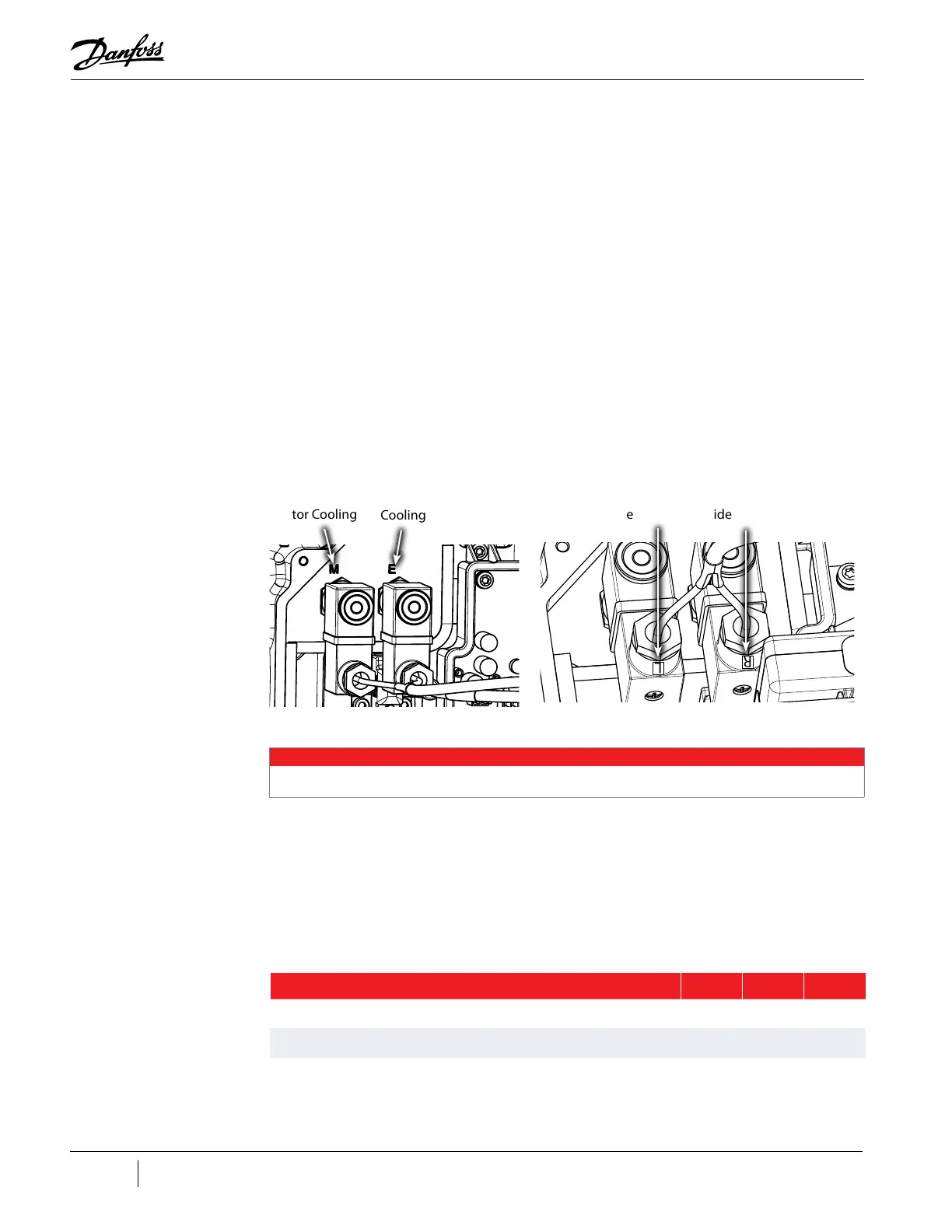
9. Install the Solenoid Coils in their proper location. For split cooling models, the coil positions
are dedicated. The right-side coil can be identified by an “R” affixed to the coil. The left-side
coil can be identified by an “L” affixed to the coil. Refer to "Figure 4-36 Solenoid Actuator Coil
Position".
Figure 4-36 Solenoid Actuator Coil Position
10. Install the Beveled Washers and Solenoid Retaining Nuts to secure the Solenoid Actuator Coils.
11. Reconnect the Solenoid Coils to J16 on the Backplane.
12. Install the compressor covers. Refer to "4.2 Compressor Covers" on page 56.
13. Return the compressor to normal operation.
4.7.4.3 Solenoid Torque Specifications
Table 4-11 Solenoid Torque Specifications
Install on left
side
R
L
Install on right
side
Motor Cooling
Electronics
Cooling
• • • CAUTION • • •
Only hand tighten the Solenoid Retaining Nuts. Do not use pliers to install.
Description Nm Ft.Lb. In.Lb.
Solenoid Tube/Plunger 4 - 35
Orifice Valve 7 - 62
Cover Screw, M5x15 1.5 - 13

 Loading...


